-
USA - English
- Locations
- SDS Access
- CTVista®+ Login

Cooling Water System Fundamentals outlined the basics of cooling tower and heat exchanger design/operation. In this chapter, we will examine cooling water chemistry and treatment programs to maintain reliability throughout the cooling water network. Cooling systems require protection from corrosion, scaling, and microbiological fouling to maximize performance.

Corrosion, scale, and biofouling control should be addressed collectively. A fourth, increasingly important factor is the potential environmental impact of water treatment chemistry, especially regarding chemicals that could appear in the plant discharge. Treatment programs that were once commonplace may no longer be allowed or may be severely restricted because of discharge regulations.
Although treatment methods serve multiple purposes, one primary objective is to protect metal surfaces. In the following sections, we review the most common corrosion mechanisms and control methods.
The typical material for cooling system piping and many heat exchanger (HX) shells is mild carbon steel. HX tubes or plates may be of stainless steel, copper alloys, titanium, aluminum, or in some cases, expensive corrosion-resistant metals. Galvanized steel fasteners are often present in cooling towers, while smaller towers may be predominantly galvanized. Most large cooling towers have concrete basins, and some still have wooden structural components. Understanding all materials in a cooling system is crucial for choosing effective corrosion control methods.
Metal corrosion is an electrochemical process in which metals in a refined state revert to their natural form. Iron is the classic example. Research indicates that the most significant iron ore deposits are located within sedimentary rocks, originating from chemical reactions between iron and oxygen in both marine and freshwater environments. The principal minerals present in these deposits are the iron oxides hematite (Fe2O3) and magnetite (Fe3O4). These ores have been extensively mined and serve as the foundational materials for nearly all iron and steel products in contemporary use.1 Iron-based materials and other metals when placed into service can be attacked in a variety of ways. The most observable way is the reaction of iron or mild steel with water and oxygen to produce rust, but other corrosion mechanisms are common. The most prevalent include:
Proper corrosion control is necessary to prolong equipment life; minimize transport of corrosion products to other locations; and at times to ensure employee safety.
The driving force for corrosive reactions is the electrical potential between the electron acceptor (the corrosive medium) and the electron donor (the metal). The following example illustrates the fundamental corrosion process. A basic laboratory experiment involves immersing an iron bar in a hydrochloric acid (HCl) solution. Bubbles form along the submerged surface of the bar, and corrosion can be observed after a short period. Figure 7.2 summarizes the chemistry.
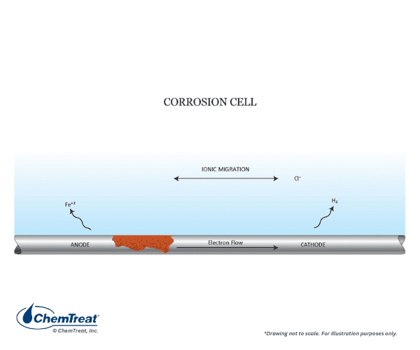
Fig. 7.2. Basic corrosion cell.
Three reactions explain the overall process:
In this case, anodes and cathodes form along the metal surface. Many hydrogen bubbles immediately form, and shortly thereafter visible corrosion appears on the entire bar. This is an example of general corrosion, where anodes and cathodes shift constantly, and it is also a classic example of an oxidation-reduction or “redox” reaction.
Each metal has a unique tendency to gain or lose electrons, and the type of corrosive agent plays a significant role. The list of half-cell metal potentials as compared to the hydrogen half-cell potential is included below.
2H+ + 2e– ⇌ H2↑ E0 = 0.00 V for a 1 molar solution by definition
The following table highlights the potentials of several of the most common metals.
Table 7-1. Half-Cell Potentials for Well-Known Metals as Compared to the Hydrogen Half Cell
| Electrode Reaction | Standard Electrode Potential (V0) |
|---|---|
| Mg → Mg2+ + 2e– | 2.363 |
| Al → Al3+ + 3e– | 1.662 |
| Zn → Zn2+ + 2e– | 0.763 |
| Fe → Fe2+ + 2e– | 0.440 |
| H2 → 2H+ + 2e– | 0.000 |
| Cu → Cu2+ + 2e– | -0.340 |
| Ag → Ag+ + e– | -0.800 |
| Au → Au3+ + 3e– | -1.420 |
From this table, we can derive several important concepts.
Regarding the common structural material of many cooling water systems, mild streel, Figure 7.3 illustrates the influence of pH, i.e., the hydrogen ion concentration.
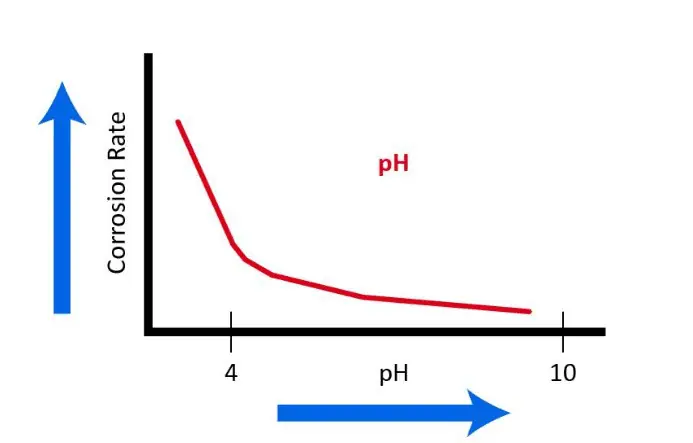
Figure 7.3. Influence of pH on mild steel corrosion rates.
Accordingly, most modern cooling system chemistry programs operate within an upper-7 to mid-8 pH range. In these conditions, a thin, passive CaCO3 layer may form to further inhibit corrosion. However, as was briefly discussed in Cooling Water System Fundamentals and will be re-examined later in this chapter, calcium carbonate scale formation can be one of the most troublesome problems in cooling systems.
If acid was the only corrodent in a cooling water system, corrosion control would be straightforward. Many cathodic reactions may occur, but oxygen reduction is most common in neutral or alkaline solutions.
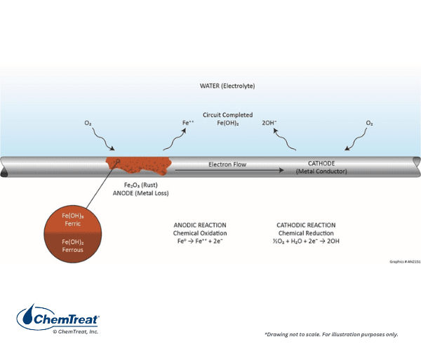
Figure 7.4. Oxygen-steel corrosion reaction.
The anodic reaction is the same as previously shown.
Fe0 → Fe2+ + 2e‒ | Eq. 7-1
Oxygen is reduced at the cathode:
½O2 + H2O + 2e‒ → 2OH‒ | Eq. 7-3
The hydroxide ions combine with Fe2+ to form ferrous hydroxide:
Fe2+ + 2OH‒ → Fe(OH)2 | Eq. 7-4
In the oxygen-laden environment, additional reactions occur. First, ferrous hydroxide will continue reacting with oxygen to form ferric hydroxide:
2Fe(OH)2 + ½O2 + H2O → 2Fe(OH)3↓ | Eq. 7-5
The reactants shown in Equations 7-4 and 7-5 are in equilibrium with other iron oxide species, as shown below:
Fe(OH)2 ⇌ FeO + H2O | Eq. 7-6
Fe(OH)3 ⇌ FeO(OH) + H2O | Eq. 7-7
Eventually, these products dehydrate to rust, which is brown-colored and offers no protection to the underlying metal:
2FeO(OH) ⇌ Fe2O3↓ + H2O | Eq. 7-8
It is also essential to recognize that, within the electrochemical process, cathodic reactions determine the rate of corrosion, whereas anodic reactions influence the specific form of corrosion that occurs. There are scenarios where a limited quantity of fixed anodes is present within a large cathodic environment. This combination can lead to severe localized corrosion and potentially rapid failures.
Upon examining Table 7.1, it is evident that magnesium and aluminum are positioned at the top, prompting consideration of their widespread application in infrastructure, including components for aircraft, electrical systems, beverage containers, and other uses. The elements are so reactive that during the production process, a tight oxide layer forms on the metal surface and protects the base metal from further corrosion. Only acids or strong alkalis will attack this protective layer, so during normal service the metals remain quite stable.
Several other important factors influence most corrosion mechanisms. These are outlined below.
Corrosion is an electrochemical process, and, as the dissolved solids concentration increases, so does the corresponding conductivity and corrosion rate.
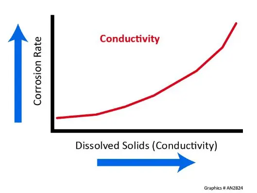
Figure 7.5. Influence of dissolved solids and conductivity on corrosion rates.
Consider cooling water in an open recirculating system that has a conductivity of 2,750 µS/cm, and compare that value to pure water with a theoretical conductivity of 0.055 µS/cm. The cooling water is 50,000 times more conductive than pure water.
Temperature commonly influences corrosion rate, and general guidelines suggest that the rate doubles with each 18°F (10°C) increase in fluid temperature. Additionally, the corrosion rate will, in general, double with each 10–20°F increase in metal skin temperature. Some processes may produce so much heat that molecular oxygen gas can form beneath deposits, exponentially influencing the corrosion process. The effect of temperature and oxygen concentration on corrosion rates is shown below.
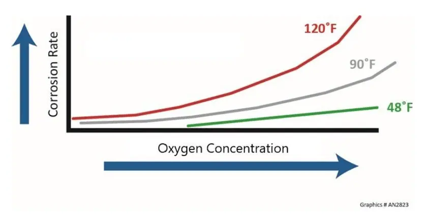
Figure 7.6. General influence of temperature and dissolved oxygen on corrosion rate.
Corrosion can be exacerbated by both elevated and diminished fluid velocities. Higher flow rates may remove protective layers of corrosion products from metal surfaces, thereby accelerating further corrosion. High velocities are also associated with erosion-corrosion, which will be discussed in this section. Conversely, low or stagnant flow conditions can increase the risk of corrosion by maintaining prolonged exposure of the metal to corrosive ions. A common guideline for linear flow rate through piping and heat exchanger tubes is 5–10 feet per second (fps), which provides a balance between corrosion/deposition control and material costs. However, every project requires careful analysis to optimize piping and equipment design and flow rates. For example, if for some reason a soft metal is needed for an application, a lower flow rate may be necessary to minimize erosion.
We will now examine the most common types of corrosion in cooling systems. Some, such as general corrosion, often allow long material life and can be controlled with straightforward treatments. Others, like pitting, have been known to cause through-wall penetrations of pipes and other equipment within months, and sometimes even weeks. Expensive unit shutdowns and material replacement may be the result.
With general corrosion, the anodes and cathodes on the metal shift constantly, and localized corrosion sites do not develop. Metal life can be quite long when general corrosion is the only issue. The figures below illustrate two examples of general corrosion.

Figure 7.7a. General corrosion of steel beams.
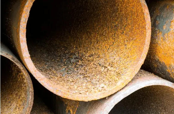
Figure 7.7b. General corrosion on the inside of a pipe
Materials selection and dimensions, such as pipe wall thickness, are often based on a 30-year life expectancy according to general corrosion calculations. For example, consider a 6” diameter Schedule 40 pipe with a wall thickness of 0.28 inches. When approximately 50 percent of the pipe wall has corroded, the pipe may be nearing failure and should be repaired or replaced. The standard unit used to express corrosion rate is mils per year (MPY), with one mil defined as one-thousandth of an inch. In this example, a general corrosion rate of 4.67 MPY would result in 50 percent wall loss over 30 years. Effective corrosion control programs can reduce overall corrosion; however, as described in the following sub-sections, localized corrosion may still occur and can be affected by several different variables.
If corrosion becomes localized, permanent anodes will develop in a large cathodic environment. Pitting, or similar mechanisms as we shall observe, is the result, as shown below.
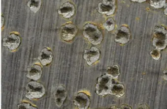
Figure 7.8. Pitting corrosion.
The corrosion rate may be the same as general corrosion, but damage is more serious because of rapid penetration of the metal at anodes. Numerous mechanisms or conditions can initiate pitting. Solids deposits on steel may produce oxygen-depleted areas. These spots are anodic to clean steel. Microbiological colonies can do the same and can also release corrosive compounds via metabolic processes. We will explore this phenomenon a bit later. Poor welding techniques can alter the chemical makeup of the metal at the weld location and increase corrosion susceptibility.
A common phenomenon with carbon steel is corrosion product (rust) accumulation over the pit.

Figure 7.9. An iron oxide tubercle covering a pit.
Reactions in a trapped liquid can raise acidity, increasing corrosion potential.
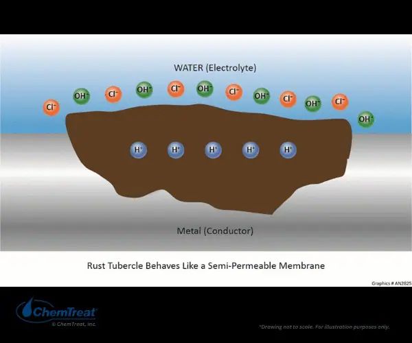
Figure 7.10. Chemistry under an iron oxide tubercle.
Chlorides or other anions diffuse into the pit to try to maintain charge neutrality, however, acidic conditions often remain. The deposits above the pit prevent bulk water corrosion inhibitors from re-passivating the metal surface within the pit.
The following figures illustrate additional pitting examples.
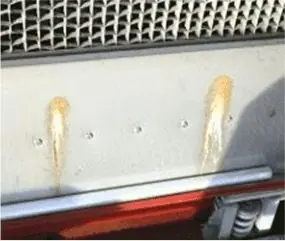
Figure 7.11a
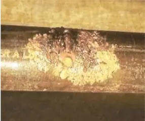
Figure 7.11b.
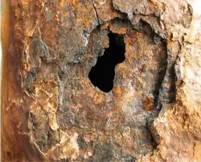
Figure 7.11c.
7.11a is pitting that has penetrated the metal basin of a cooling tower. 7.11b shows corrosion products on the outside of a pipe that was generated by internal attack and resulting through-wall penetration. 7.11c illustrates another through-wall penetration.
For carbon steel pits covered or filled with corrosion products, if the material is black (typically due to the presence of magnetite (Fe3O4)), the pit is active and the corrosion process is ongoing.
Chloride pitting of stainless steels can occur in various settings, such as open recirculating systems where cooling tower evaporation (see Cooling Water System Fundamentals) leads to an increase in dissolved solids concentration. The two most popular stainless steels (SS) for steam surface condenser tubes are 304 and 316, and often one or the other is specified for a project without the designers giving thought to the chloride concentrations the materials will see. Stainless steels form an oxide coating that protects the base metal, but significant concentrations of chloride will penetrate the oxide layer and initiate pitting. For years, the recommended maximum chloride levels for these steels ranged from 500 ppm for 304 SS to 3,000 ppm for 316L SS at ambient temperature. Research has subsequently shown that these limits were too high, and one noted materials expert suggests 100 and 400 ppm, respectively, for clean tubes. Note the emphasis on clean tubes. Deposits exacerbate the corrosion potential. Additionally, temperatures above ambient greatly influence the potential for chloride-induced stress corrosion cracking (SCC) of austenitic stainless steels, which can be of huge concern in industries such as petroleum refining that have many heat exchangers for production of numerous compounds. SCC is examined shortly.
Resistance to chloride pitting is often a primary factor in heat exchanger materials selection. A well-known guide is the pitting resistance equivalent number (PREN) chart as shown below.
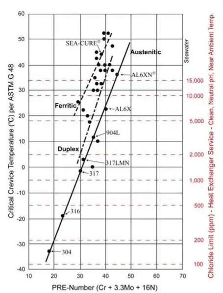
Figure 7.12. PREN chart. Illustration courtesy of Dan Janikowski, Plymouth Tube Company.
Higher-alloy materials beyond the 300 austenitic stainless series are recommended for cooling waters with appreciable chlorides. For highly brackish waters and seawater, the ferritic and super-ferritic alloys, e.g., SEA-CURE®, are often required.
Crevice corrosion is a mechanism that develops at the crevices of mechanical joints, e.g., flange gaskets, the rolled ends of tubes, bolt connections, or at other locations including the boundaries of deposits. Figure 7.13 shows an example of crevice corrosion.
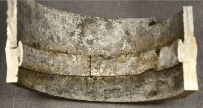
Figure 7.13. Crevice corrosion under ring at left side on pipe surface.
Water stagnates in these locations and can become oxygen depleted, which then makes the crevices anodic to the other metal. Like pitting, the corrosion is localized.
Often, crevice corrosion is not discovered until a scheduled outage or if the corrosion causes an equipment failure. The best approach to avoid crevice corrosion is to eliminate the crevice. Proper chemical treatment will minimize deposit and crevice formation from that source, but for equipment that is mechanically coupled, care is needed in the design phase to eliminate crevices when possible. Installing water-impermeable gaskets at flange connections may be a solution in some applications, for example.
A phenomenon that has plagued numerous water-cooled heat exchangers is manganese-influenced pitting, with many problems reported along the Ohio River. Even at concentrations as low as 0.02 ppm, dissolved manganese in cooling water can be oxidized to manganese dioxide (MnO2) by chlorination. A thin, varnish-like coating will appear on the heat exchanger surfaces.
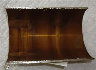
Figure 7.14. Varnish-colored coating of manganese dioxide on a tube wall.
The manganese deposits are strongly cathodic to the underlying metal and can cause severe localized corrosion.
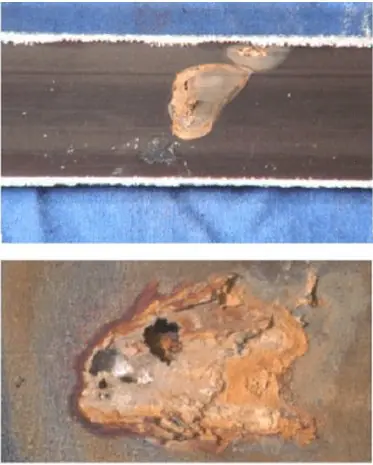
Figure 7.15a and b. Manganese-induced pitting on tubes subjected to periodic heavy chlorination.
304 and 316 SS are susceptible to manganese deposit corrosion, but it can also affect admiralty brass, aluminum brass, and cupro-nickel. Attack is likely if the manganese content of the deposit exceeds five percent. A concentration greater than 20 percent will result in severe pitting.
MnO2 formation can be affected by factors such as elevated pH, aeration, and occasionally the catalytic properties of the metal surface. Furthermore, the MnO2 layer can be oxidized to permanganate (MnO4) by chlorine. Permanganate dissolves the base metal, and in the process is reduced back to MnO2. The cycle repeats during each chlorination. Manganese corrosion is apparently not a major problem with mild steel, possibly because other corrosion products prevent manganese from forming a uniform and dense deposit.
Manganese deposition and corrosion control methods include limiting or eliminating oxidizing biocide feed (potentially by switching to non-oxidizing biocides), and application of an effective manganese stabilization program. Selection of corrosion resistant materials in the design phase is another approach.
If the cooling water contains significant suspended solids, gas bubbles, or if the velocity is simply too high, the flowing fluid can strip the protective oxide layer on metals and allow continuous corrosion.

Figure 7.16. Erosion corrosion at a pipe elbow.
For example, in one flow study of seawater on mild steel, the following corrosion rates were measured:
Table 7-A: Linear Velocity and Corrosion Rates of Seawater on Mild Steel
| Linear Velocity (ft/sec) | Corrosion Rate (mpy) |
|---|---|
| 1 | 7 |
| 4 | 15 |
| 17 | 35 |
Soft metals, such as Admiralty brass, are the most susceptible to erosion, especially at flow disturbances such as the inlet end of heat exchanger tube sheets. These issues must be accounted for during project design.
Cavitation is a specific type of erosion corrosion that most commonly affects centrifugal pump impellers.
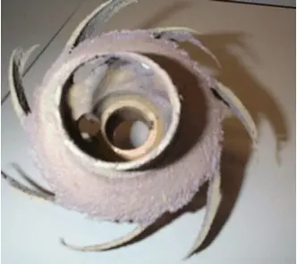
Figure 7.17. Severe cavitation damage of a pump impeller.
If insufficient pressure is available at the pump suction (inlet pressure is termed “net positive suction head (NPSH)”), bubbles in the water may collapse. The collapsing bubbles can generate very large, localized forces that strip protective oxide and damage the metal. Other potential locations for cavitation include valve discharge, regulators, orifices, or other locations of pressure drop. Potential cavitation issues should be addressed in the project design phase to ensure that pumps and other equipment have sufficient head pressure.
Most metals used in standard applications like piping, heat exchangers, and related equipment consist of multiple small crystals or grains rather than forming a single crystal structure.1 The grain structure has a huge impact on metallurgy and several corrosion mechanisms.
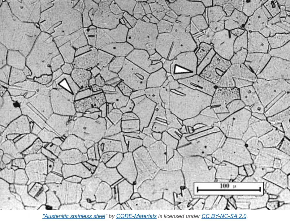
Figure 7.18. Scanning Electron Microscope (SEM) photo of the microstructure of a low-carbon steel pipe wall. The grain boundaries are plainly evident.
A simple illustration of material fatigue can be observed by repeatedly flexing a paperclip or wire until it ultimately breaks or fractures. The fractures often align along grain boundaries. Plant equipment that repeatedly cycles in load may suffer from fatigue. The corrosion typically begins as micro-fissures that grow larger over time. Research suggests that fatigue can also frequently occur across grains, i.e., transgranular.
Fatigue may be accelerated if the metal is immersed within a corrosive environment, even basic process waters. As fissures develop, corrosion products (often just oxides of the base metal) can build up within the cracks and exacerbate crack growth. This is corrosion fatigue.
Other intergranular corrosion mechanisms beyond fatigue may be quite problematic, as relatively small metal loss can cause a disproportionate reduction in metal strength.
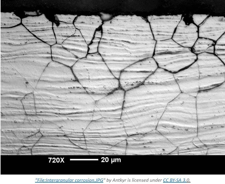
Figure 7.19. Intergranular corrosion
Intergranular corrosion is localized attack that occurs at the grain boundaries, where relatively little metal loss can cause a disproportionate reduction in metal strength. The most well-known mechanism is stress corrosion cracking (SCC), and it can be particularly troublesome in high-temperature applications. (See Fundamentals of Industrial Boilers and Steam Generating Systems).
SCC requires some type of metal stress, but where the stress can be either internal or applied.
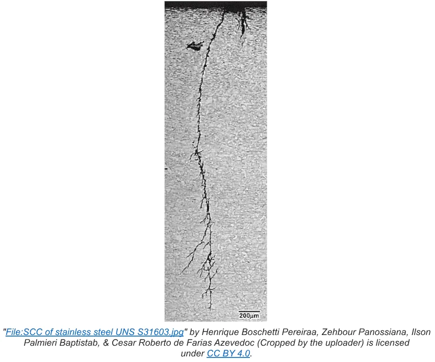
Figure 7.20. Stress Corrosion Cracking
Internal stress usually appears during the fabrication process. A common example of applied internal stress is cold work or cold rolling of steel to shape it for a particular specification. Seamed pipe is a well-known example. Heat treatment/annealing is often utilized to relieve stresses induced by cold working.
Weak spots generated by stress can develop into micro-fissures that then become susceptible to corrosive agents in the water. Perhaps the most well-known example is chloride-induced SCC of stainless steel. At stress points, anodes develop, which are surrounded by non-stressed metal that serves as the cathode.
Common locations for SCC in cooling water systems include threads cut into nuts and bolts, rolled tubes at tube sheets, drilled or punched holes in distributor piping, and pipe elbows where the metal has been mechanically worked.
SCC can be mitigated by heat treatment stress relief. However, it is not always practical to heat relieve every potential location. During equipment inspections, identified or suspected stressed material should receive special attention to determine the efficacy of chemical treatment programs in minimizing corrosion.
Intergranular and stress corrosion susceptibility is often greater at welds. For chromium-alloy steel, the welding process can cause the precipitation of chromium carbides that generate chromium depleted spots within the metal. These become anodic to the base metal and become susceptible to localized corrosion. Many failures have occurred at weld seams in plant water systems. Selection of the correct weld filler material is also important. An under-recognized problem is use of a filler material that has different thermal expansion properties than the base metal. Mechanical fracture may result.
Galvanic corrosion occurs when two different metals are in physical contact within the cooling water environment. Refer to Table 7-1, which lists the electrochemical potentials for several commonly used metals in cooling water infrastructure. When two metals are paired, the one with greater reactivity becomes anodic relative to the less reactive metal. The larger the separation in electrochemical potential, the greater the potential corrosion rate. A common example is shown in the figure below.
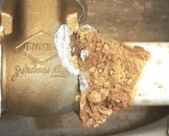
Figure 7.21. Galvanic corrosion of a steel pipe attached to a brass valve.
Galvanic cells can form as a result of chemical reactions that take place within a fluid. The manganese pitting corrosion mechanism outlined earlier was one example. Another common mechanism occurs in systems that have both steel and copper alloys, even if they are not physically connected. If the conditions allow some copper corrosion, the copper may plate out on the steel and produce a galvanic corrosion cell.
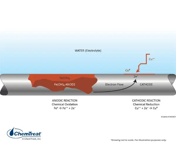
Figure 7.22. Galvanic corrosion induced by copper plating on steel.
This example illustrates the use of data from Table 7.1 by analyzing the reaction through the half-cell potentials.
|
Fe → Fe2+ + 2e– |
V0 = 0.440V |
|
Cu2+ + 2e– → Cu |
V0 = 0.340V |
| E0 = 0.780V |
A strong driving potential exists for this reaction.
The ideal solution to galvanic corrosion is to not have mixed metallurgies in cooling systems, but this arrangement is usually impractical. A key is having a small ratio of the more electronegative material, e.g., copper, in a system with a much larger amount of the electropositive material, e.g., steel. While galvanic corrosion can still occur, the large anode to cathode ratio ensures that the attack is spread out over a large area and does not cause severe damage.
In other cases, special fittings or connections may be employed to physically separate different metals.
Figure 7.23 illustrates the use of a di-electric union to separate copper from steel.
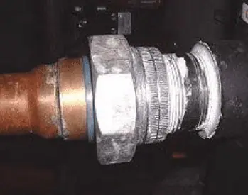
Figure 7.23. Blue plastic dielectric union separating copper and steel.
A unique form of corrosion that sometimes occurs in heat exchanger tubes is dealloying. The most common example is dezincification of admiralty brass. Admiralty brass is composed of 70 percent copper, 29 percent zinc, and a small amount of tin, which is added to reduce the likelihood of dezincification. Nevertheless, dezincification can still take place. Figure 7.24 shows an admiralty tube that has experienced zinc loss.
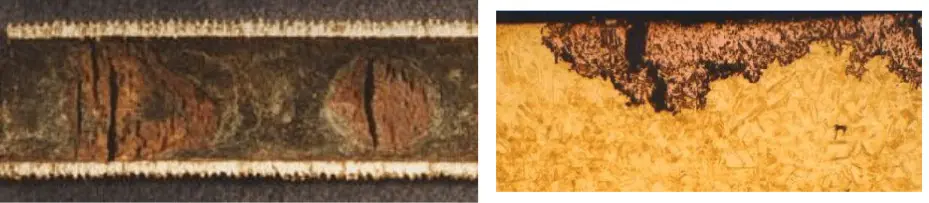
Figure 7.24a and b. Top view of dezincification and a photomicrograph of a tube section.
Two types of dezincification have been postulated; plug and layer. In either case, zinc departs from the metal substrate resulting in porous and brittle copper that is not structurally sound. Visually, the attack appears as a dull red patch on the yellowish copper metal.
The actual dezincification mechanism is still highly debated. One theory is that both metals corrode, with copper redepositing. The other is that zinc selectively leaches out of the alloy. The following conditions can enhance dezincification.
Microbiologically induced corrosion (MIC) is a process in which microorganisms initiate, facilitate and/or accelerate corrosion reactions. Cooling systems provide an ideal environment for microorganisms to establish colonies and form slimy, mud-like deposits. (Additional details are provided in the microbiological control section later in this chapter.) In the first place, deposits can cause oxygen differential corrosion as outlined earlier. Beyond this issue, however, is that the metabolic processes of some microbes generate compounds that directly attack metals. For example, iron-oxidizing bacteria such as gallionella produce ferric chloride, which is known to accelerate pitting. Sulfate reducing bacteria (SRB) such as desulfovibrio desulfuricans extract oxygen from sulfate (SO4) to produce hydrogen sulfide (H2S). Sulfides in just about any form are quite corrosive to many metals.
MIC can leave smooth gouges in the metal surface as shown in Figure 7.25 below, and it can also cause rapid pitting of some materials, including the 300-series stainless steels.
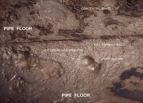
Figure 7.25. MIC example
So far, much of the discussion has been about steel corrosion, as steels make up most of the metal in cooling systems. However, other metallic and non-metallic materials are often present, and these can suffer from corrosion, too. The following sections examine corrosion issues for the most common of these materials.
Copper alloys are the second most common material in cooling water systems, typically for heat exchanger tubes. They have a higher thermal conductivity than steel, are naturally toxic to many aquatic species, and are more resistant than steel to some corrosion mechanisms.
As demonstrated in Table 7.2, copper is considered noble relative to the hydrogen ion, and consequently, it exhibits minimal susceptibility to corrosion in acidic environments. However, oxygen is more reactive than H+, and in cooling water systems copper alloys will initially develop a cuprous oxide (Cu2O) multi-layer of variable porosity, where copper exists in the +1 valence state.
2Cu + O2 → Cu2O | Eq. 7-9
Over time, and in the continued presence of oxygen or other oxidizing agents, further oxidation of the outer cuprous oxide layer can take place to produce a grayish-black layer of cupric oxide (CuO).
Cu2O + ½O2 → 2CuO | Eq. 7-10
In some cases, the cupric oxide layer may remain protective, but certain compounds, and most notably ammonia, can be very corrosive. It dissolves cupric ion through a mechanism known as d-orbital bonding.
Cu2+ + 4NH3 → Cu(NH3)42+ (aq) | Eq. 7-11
For makeup waters containing a significant concentration of ammonia, e.g., wastewater treatment plant effluent, corrosion of copper-alloy condenser or other heat exchanger tubes may be of significant concern. Copper-alloy corrosion has sometimes been problematic in steam systems where ammonia is utilized for condensate and feedwater pH control.
Another impurity that can cause enormous damage to copper alloys (and other metals) is sulfide, which, as has been noted may come from microbiological colonies that contain sulfate reducing bacteria.
Cu2+ + H2S → CuS↓ + H2↑ | Eq. 7-12
Other potential sulfide sources include water that has been allowed to go septic, and from process leaks at refineries and similar plants. A startling example occurred a number of years ago, when the aging 90-10 Cu-Ni tubes in a steam surface condenser were replaced, only to have the new tubes fail from pitting attack within 18 months of commissioning. Investigation revealed that the tube fabricator utilized a lubricant containing sulfide, but did not remove the compound before shipment to the plant. The sulfide deposits did not wash off but burrowed into the metal in thousands of spots.
A different but very recognizable copper corrosion product is copper carbonate (CuCO3). This bluish/green verdigris (also called patina) is often seen on weathered copper-alloy structures such as roofing, plaques and statues, and is typically part of the architectural design of the structures.

Figure 7.26. Statue of Liberty with blue/green patina.
The basic chemistry is:
2Cu + H2O + CO2 + O2 → Cu(OH)2 + CuCO3↓ | Eq. 7-13
The color can be somewhat variable depending upon the degree of hydration of the film.
Referring again to Table 7.2, zinc is anodic to almost all metals except magnesium and aluminum. Unlike those two metals, though, it does not form a super-strong oxide layer. Rather, via the galvanizing process where a zinc coating is applied to steel surfaces, the zinc serves as a sacrificial anode to iron.
The process of galvanizing has been utilized since 1742. Much of modern galvanizing is by hot dipping, although continuous processes such as heavy mill galvanizing are common for sheet steel. Hot dipping is a batch process in which newly fabricated steel components are immersed in a solution of molten zinc for a prescribed time. The zinc fuses to the steel surface. The coating thickness is directly proportional to the immersion duration, which can be adjusted for component size and application.
Newly galvanized materials are often shiny and very reflective as shown in Figure 7.27.

Figure 7.27. Freshly galvanized metal.
However, not all galvanized coatings are shiny. Some elements in the steel, e.g., silicon and phosphorous, can accelerate the growth of zinc-iron alloy layers. This may produce a finished galvanized coating consisting entirely of zinc-iron alloy.

Figure 7.28. Grayish roadside guardrails.
The formation of the protective dark gray patina (surface finish) begins with the development of a thin layer of zinc oxide on the surface. Under proper conditions, these oxides will incorporate a layer of basic zinc carbonate when in contact with water. Following initial exposure to water and carbon dioxide (which can be achieved by allowing new galvanized cooling system components to experience outdoor conditions over a period of several months), industrial galvanized components can then be exposed to system water. The conditioning step requires careful control to produce a hydrated zinc carbonate compound thought to have the following formula:
3Zn(OH)2∙ZnCO3∙H2O
This layer grows and becomes more protective over time, but if the proper water chemistry is not established during the conditioning process, a non-protective material known as “white rust” can form. Further details regarding zinc passivation chemistry are examined in a later section on pre-operational startup of cooling systems.
Galvanized components are common in many cooling tower locations, even if the main support structure is wood or plastic.
Many commercial cooling towers of modest size may be completely fabricated from galvanized steel.
Figure 7.29. A package galvanized cooling tower.
Referring to Table 7.1 from the beginning of this chapter, it may seem counterintuitive that aluminum, and in certain cases magnesium, are appropriate materials for construction, given their high reactivity. The key is that the high reactivity induces formation of a tight oxide layer that protects the metal underneath. Typical aluminum products include injection molds, engine blocks, radiators, cooling tower ladders and walkways, handrails, fan blades and other similar components. Aluminum is resistant to atmospheric corrosion and that aspect, coupled with its light weight, make it an excellent material for airplane components.
Aluminum is an amphoteric material meaning that it will corrode at low and high pH.
Aluminum can corrode in waters made alkaline with phosphate. Also, because aluminum is the more active electrochemically than steel, it will corrode when coupled to steel in cooling water environments.
This section provides a brief overview of two non-metallic corrosion issues commonly associated with large cooling towers: the deterioration of wood, which can function as the tower’s support structure, and concrete, a typical material used for cooling tower basins.
Wood deterioration can generally be classified into three categories, physical, chemical, and microbiological.
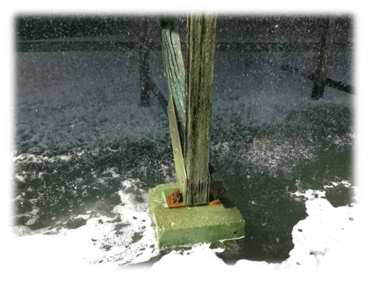
Figure 7.30. An example of iron rot on wooden components.
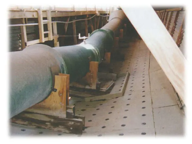
Figure 7.31. Excessive weight loading on distribution deck (36” header)
The following discussion outlines the three primary types of fungal wood rot.
Brown Rot: Brown rot, also known as dry rot, is more common in soft woods, and attacks beneath the preservative layer applied during fabrication. The fungi go after cellulose, leaving dark-colored lignins behind. It can penetrate deep into the wood.

Figure 7.32. Brown rot.
White Rot: White rot is more common in hard woods, and attacks lignins. It progresses more slowly than brown rot. The wood surface becomes soft and stringy and appears bleached. White rot can be controlled by surface fungicide treatments in early growth stages. The fungicide penetrates slowly into the wood.
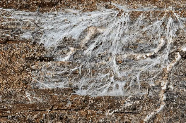
Figure 7.33. White rot.
Soft Rot: Soft rot occurs only in water-washed areas and is confined to the surface in early stages. The attack is slower than white or brown rot. The surface appears cracked and light-colored when dry. Soft rot can be controlled by diligent cooling water microbiological treatment.

Figure 7.34. Soft rot.
Concrete was used to build large hyperbolic cooling towers at nuclear and some coal plants in the last century. Virtually no hyperbolic towers have been constructed in the last several decades and will not be considered further here. However, many of the large, mechanical draft towers in heavy industry and power have reinforced concrete basins.
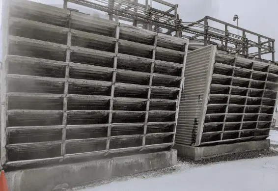
Figure 7.35. Cooling Towers Constructed with Concrete Basins. Source: Rain Carbon Chemical Plant Prospect Survey – Jason Miklavcic – December 20, 2020.
Concrete is strong, poured on site, and can have a long life. Plants using sulfuric acid to control cooling water pH often face issues when the acid is injected undiluted into the basin. Commodity-strength sulfuric acid (93–98 percent concentration) has a density almost twice that of water and will sink rapidly to the basin floor if not diluted, where it can attack the concrete and concrete-reinforcing bars.
The primary method to minimize this damage is an acid dilution system, which externally mix acid and water. Distribution of the mixture is performed through a trough above the basin.
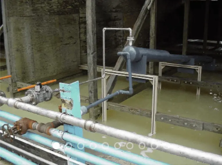
Figure 7.36. Acid dilution piping and trough above a cooling tower basin. Photo courtesy of Global Treat, Inc. of Spring, Texas.
Standard Portland cement can be attacked by waters with a high sulfate concentration (>1,500 ppm), which is possible in some cooling systems per the concentrating effect of the tower. This issue can be addressed in the design phase with careful calculation of the makeup water quality and the extent to which sulfate will concentrate when the tower is cycled up to normal levels. Conditions may require the use of Type V Portland cement, which has a reduced amount of tri-calcium aluminate, ordinarily one of the primary components of standard cement.
Before discussing corrosion control, we’ll first address the primary causes of deposition and scaling in cooling systems. Since water treatment programs typically combine corrosion and deposit inhibitors, these topics are often discussed together.
Apart from scale formation, solids deposition in cooling systems can occur by several additional mechanisms, including:
One common restricted-flow location, outlined in Cooling Water System Fundamentals, is cooling tower fill. High-efficiency film fill provides excellent heat transfer but at the price of a torturous flow path that reduces water velocity. Throttled flow to heat exchangers can also establish low-flow zones that collect solids. An often-overlooked item with large cooling systems are dead legs that can accumulate materials, including microbes.
Cooling towers are superb air scrubbers, and many solids may be introduced through that flow path. Dust ingression during dry periods is a common problem. Another example with which many operators are familiar is intrusion of cottonwood seeds and additional leafy vegetation that clog strainers and other equipment.
Water and air are filled with microbes that can potentially form troublesome colonies throughout cooling systems. Fouling can occur very rapidly and potentially force unit derating or equipment shutdown within days of the microbial onset. The protective slime secreted by some microbes easily traps suspended solids that convert the material into a mud-like product.
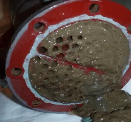
Figure 7.37. Slime/silt fouling in a heat exchanger.
Aquatic creatures that escape cooling water inlet screens can block the inlet ends of heat exchanger tubes. This has been particularly problematic in once-through power plant steam surface condensers. Some of the most common creatures include Asiatic clams, zebra mussels, and even small fish such as shad.
Many large industries have numerous heat exchangers. Heat exchanger leaks may introduce contaminants to the cooling water return to the tower. Particularly troublesome are oils and heavy hydrocarbons that can coat cooling system equipment.
Corrosion is problematic in its own right, but corrosion releases products that then lodge in other locations.
Makeup Water Pretreatment Methods included discussion about solubility products, and how when various dissolved ions reach a solubility limit, solids precipitation occurs. This is the mechanism behind scale formation in water systems.
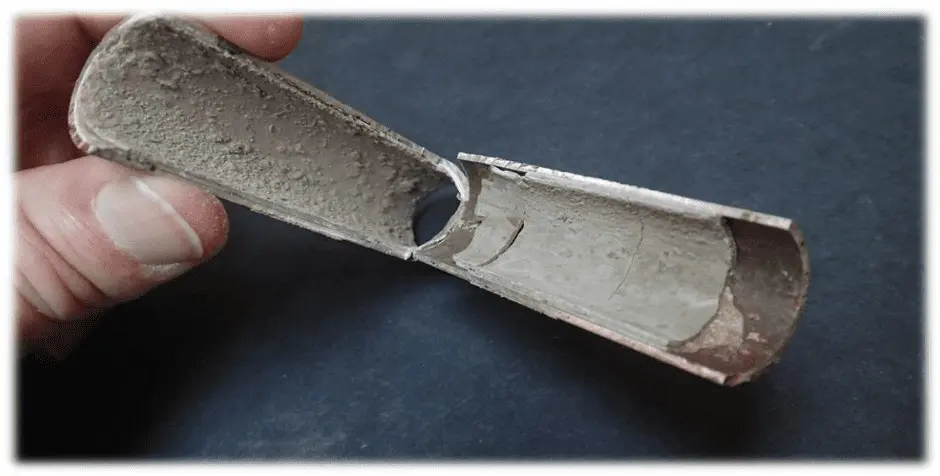
Figure 7.38. Cross-section of a heat exchanger tube showing calcium carbonate scale formation.
In Makeup Water Pretreatment Methods, we learned that the most common precipitate in natural waters is calcium carbonate (CaCO3), and how CaCO3 precipitation chemistry can be used advantageously in lime softening reactions for makeup water treatment. The buildup of calcium carbonate scale in water systems, such as home plumbing, has long challenged water treaters and led to the development of modern scale-control chemistry. To review briefly, almost all natural waters contain dissolved calcium ions (Ca2+) and bicarbonate alkalinity (HCO3–). Because of various influences, including temperature, the ions will precipitate from solution. The following reaction is representative of this process.
Ca2+ + 2HCO3– + heat → CaCO3↓ + CO2↑ + H2O | Eq. 7-14
Calcium carbonate has three polymorphs. Calcite is the thermodynamically most stable form, and comprises most natural deposits.
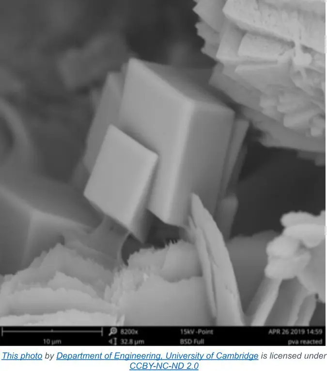
Figure 7.39. Calcite crystal
A less stable form is aragonite, which is mainly found in biosynthetic CaCO3, such as shells and corals. The final structure is vaterite, which rarely occurs in nature, but plays an important transitional role in calcium carbonate formation from solution.
Calcium carbonate deposition was the driver for the development of the first programs to predict scale-forming (and corrosion) tendencies of water impurities. These developments are highlighted below.
Langelier Saturation Index (LSI)
In 1936, Dr. Wilfred F. Langelier (1886–1981) was researching a corrosion problem in the water supply piping for Cleveland, Ohio. He learned that corrosion could be reduced by raising the treated water pH, but with the tradeoff of increased potential for calcium carbonate scaling.
He developed the LSI; an equilibrium model derived from the theoretical evaluation of calcium carbonate saturation. Water is said to be at saturation with calcium carbonate when it will neither dissolve nor precipitate the mineral. His calculations could predict when calcium carbonate scaling would occur by measuring the concentrations of calcium, bicarbonate alkalinity, pH, and total dissolved solids throughout the common water temperature range.
The fundamental equation is:
LSI = pH – pHs | Eq 7-15
Where;
pHs = (pK2 ‒ pKs) + pCa + pAlk Eq 7-16
The values for pK2 and pKs are a function of temperature. As the LSI technique gained favor, researchers developed nomographs that allowed quick calculation of (pK2 ‒ pKs) within typical once-through or open-recirculating temperature ranges.
The empirical correlation of the calculations is summarized as follows:
Langelier was able to control corrosion while avoiding scale formation by adjusting lime feed to maintain a +0.5 to +1.0 LSI range in the city water.
For once-through and closed water systems, alkali addition to increase the LSI to 0.5 or thereabouts can minimize corrosivity but not reach severe scale-forming conditions. In a recirculating cooling system, it may be possible to raise the LSI or the other indices outlined below by increasing the cycles of concentration, which increases the calcium hardness and carbonate alkalinity.
Ryznar Stability Index (RSI)
In 1944, John W. Ryznar (1912–1996) proposed a substantial modification to the LSI. He found that it was possible for both low hardness and high hardness waters to have the same LSI depending on the alkalinity and related pH. Ryznar named his relationship the Stability Index and substantiated his RSI with experimental data. The Ryznar equation employs the same data as the LSI, but the final calculation is:
RSI = 2pHs – pH | Eq 7-17
The empirical correlation of the RSI is summarized as follows:
Practical Scaling Index (PSI)
The Practical Scaling Index (PSI) was developed by Paul Puckorius (1930–2019), who, when young, was an assistant of Ryznar’s. It incorporates a calculated pH of the water based on buffering capacity, instead of simply measured pH. The practical scaling index (PSI) equation is:
(PSI) = 2(pHeq) ‒ pHS | Eq. 7-18
pHeq = 1.465 x log10 (total alkalinity) + 4.54 | Eq. 7-19
The PSI empirical correlation is the same as RSI. A leading combustion turbine manufacturer employs PSI as a method for assessing scaling tendencies in inlet air coolers. Incorporating these calculations into a spreadsheet application is a simple and efficient process.
Other predictive indices are available, including the Oddo-Tomson Index, Stiff-Davis Index, Saturation Levels, Momentary Excess, and others. It is helpful to introduce one other calculation, the Larson-Skold index for corrosion potential. Aggressive anions like chloride and sulfate are more electrically conductive than the buffering anions, bicarbonate and carbonate. In the 1950s, Dr. T. E. Larson and Dr. R. V. Skold studied the corrosivity of Great Lakes waters and developed the following formula.
Larson-Skold Index = (epm Cl– + epm SO42-)/(epm HCO3– + epm CO32-) Eq. 7-20
(epm = equivalents per million)
They found that when the ratio of strong anions to weak anions was less than 0.2, the buffering anions have a greater influence than the corrosive anions and can form a natural inhibitive film. However, when the index rises above 0.6, the situation is reversed and the potential for corrosion is greater. The Larson-Skold empirical relationship was specifically based on Great Lakes waters. Although similar relationships can be calculated for other waters, the predictions may be different.
While some water treatment companies still use these calculations for quick evaluation of water scaling tendencies, the methods lack the capabilities of modern computer programs, which account for additional factors, including the common ion effect. Sophisticated programs are available that allow the user to input system conditions and raw water chemistry, as well as scale inhibitor types and concentrations. The programs will calculate normal range and boundary conditions for any desired treatment program. The next sections examine additional scaling mechanisms.
Depending upon the chemistry of the makeup water, or how it changes when cycled up in a cooling tower, other mineral deposits are possible in cooling systems. Table 7-2 outlines the most common.
Table 7-2. Other Common Cooling Water Scale Deposits
| Compound | Formula |
|---|---|
| Gypsum | CaSO4∙2H2O |
| Silica | SiO2 |
| Magnesium Silicate | MgSiO3 |
| Calcium Phosphate | Ca3(PO4)2 |
| Fluorite | CaF2 |
Scaling issues, particularly those associated with sulfate and phosphate deposition, have primarily resulted from modifications or improvements to chemical treatment programs.
It’s important to note that the mineral compounds in Table 7-2 differ from CaCO3, which contains the CO3 anion—the conjugate base of H2CO3. While a detailed discussion of acids and bases is outside this book’s scope, the primary point is that carbonate deposits are typically removable with even dilute acid.
CaCO3 + H2SO4 → Ca2+(aq) + SO42-(aq) + H2CO3 | Eq. 7-21
H2CO3 ⇌ CO2↑ + H2O | Eq. 7-22
Thus, if acid is supplied in sufficient quantities with uniform contact, CaCO3 deposits will entirely dissolve as the carbonate converts to carbon dioxide. Sulfuric acid feed to cooling tower makeup was, and in some cases still is, a common method to reduce alkalinity and lower the potential for CaCO3 scale formation. Acid feed requirements are often not large enough to cause calcium sulfate precipitation, but the issue cannot be ignored.
Calcium Sulfate
An often problematic issue is gypsum (CaSO4∙2H2O) scaling, influenced by either elevated sulfate concentrations in the makeup or from acid treatment to remove carbonate.
Calcium sulfate has higher solubility than CaCO3, as shown below.
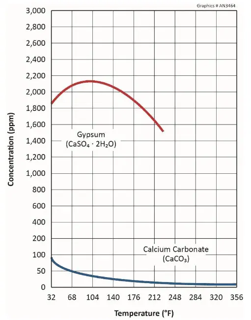
Figure 7.40. CaCO3 and gypsum solubilities as a function of temperature.
The figure reveals that gypsum also exhibits reverse solubility, but not until temperatures reach approximately 105o F.
A common general guideline suggests limits of 1,200 ppm calcium (mg/L as CaCO3) and 1,200 ppm sulfate (mg/L as SO4), or some multiple thereof, to prevent scale formation at normal cooling system temperatures in untreated water. Higher limits may be possible with chemical treatment, but these cases should be evaluated on an individual basis.
Calcium Phosphate
As will be outlined in greater detail in the next section, in the 1980s a major shift in chemical treatment of open-recirculating systems occurred with the adoption of inorganic and organic phosphate chemistry for both scale and corrosion control. Suddenly, tricalcium phosphate (Ca3(PO4)2) deposition became a major problem at many facilities.
Besides tricalcium phosphate (Ca3(PO4)2), other calcium phosphate phases can form in cooling water. It is often assumed that the thermodynamically stable hydroxyapatite (Ca5(PO4)3(OH)) is a suitable prototype for scale prediction. It seems that during the precipitation of calcium phosphate, amorphous calcium phosphate (ACP) forms first followed by the nucleation and phase transformation of other compounds.
ACP → Precursor → Stable Phase
Calcium phosphate(s) solubility is strongly dependent on solution pH and temperature. All species show inverse solubility with respect to those two parameters. The scaling tendency of calcium phosphate is also dependent on other influences, including those from other metal ions. All factors must be considered when calculating scaling potential.
Silica/Silicates
The aqueous chemistry of silica is complex, and any number of precipitates may form depending upon temperature, pH, and other factors. Potential deposits include:
Amorphous silica is simply SiO2. Many surface waters contain low levels (<15 ppm) of silica, however, some groundwaters can have concentrations as high as 75–80 ppm. At ambient temperature, the silica saturation level is around 150 ppm, so as the concentration of silica increases to saturation and above, a polymerization process induces formation of colloidal silica that can attach to system surfaces. This deposition mainly occurs in the coolest locations, such as tower fill.
In the pH range of approximately 2.0–8.3, silica solubility is independent of pH, however, dissolved silica converts to silicate (SiO3–) as pH rises above 8.3. Silicates will precipitate with cations, most notably magnesium and calcium. These compounds exhibit inverse solubility with respect to pH and temperature, and will first accumulate in warm locations, i.e., heat exchangers. Silica and silicate scales are tenacious and difficult to remove. They are also strong insulators that significantly reduce heat transfer.
Some chemical treatment programs may allow operation with dissolved silica concentrations at or even above 200 ppm. However, thorough knowledge of the water chemistry is necessary to push beyond this concentration. For example, polyvalent ions, such as Zn2+ and Al3+, are surrounded by hydroxyl groups that can catalyze silica polymerization. Among all cations, magnesium has the greatest potential to induce silicate deposition.
Dissolved silica can be analyzed by ultraviolet/visible (UV/VIS) spectrophotometry via the molybdate method. Total silica measurement, including the colloidal form where silica exists as solid particles, requires more advanced techniques, such as inductively coupled plasma (ICP) or atomic absorption (AA) spectroscopy.
Chemical treatment methods for corrosion and scale control have been intertwined for years. This section provides a review of the most common programs over the last half century or more, and how past and present methods have been designed to address both issues.
Refer to Equation 7-14. In the middle of the last century, a hugely popular treatment program for open-recirculating systems was sulfuric acid feed for scale control (to establish a common pH range of 6.5–7.0), with feed of disodium chromate (Na2Cr2O7) for corrosion control. This latter compound provides chromate ions (CrO42-) that react with carbon steel to form a pseudo-stainless steel layer that can be quite protective.
However, in the 1970s and 1980s, dawning recognition of hexavalent chromium (Cr6+) toxicity led to a ban on chromium discharge to the environment, which essentially eliminated chromate treatment for open cooling water systems. The replacement program was quite different, with a key concept being operation at a mildly basic pH (typically around 8.0 or perhaps a bit higher) to assist with corrosion control. The core treatment chemicals became inorganic and organic phosphates. But, as we shall see, this more complicated chemistry (as compared to acid-chromate) increased scaling potential. Figure 7.41 succinctly illustrates the general relationship between corrosion and scaling.
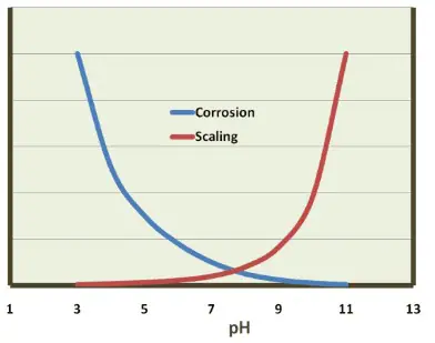
Figure 7.41. General relationship between corrosion and scaling as a function of pH.
The ability of phosphate to influence pH is shown by the reaction of tri-sodium phosphate (Na3PO4 , TSP) in water.
Na3PO4 + H2O ⇌ NaH2PO4 + NaOH | Eq. 7-23
TSP chemistry has been utilized for decades to adjust pH in high-pressure steam generators (refer to Fundamentals of Industrial Boilers and Steam Generating Systems). Applying inorganic phosphates alone to cooling water can cause significant Ca3(PO4)2 buildup, and switching from acid-chromate to phosphate chemistry led to major calcium phosphate deposition issues. Accordingly, formulations emerged that included polyphosphates, organic phosphates (aka phosphonates), polymers, and often a small concentration of zinc, all designed for integrated scale and corrosion control.
The optimum residual phosphate concentration depends on factors such as the LSI/RSI/PSI Index of the water, pH, temperature, and the type of other inhibitors in the treatment program. Too much phosphate can result in tri-calcium phosphate scaling on hot surfaces. Phosphate can also precipitate with iron and aluminum.
A typical orthophosphate control range is 6–18 ppm.
Polyphosphates contain multiple phosphorus atoms connected to each other through oxygen bridges as shown in Figure 7.42. Polyphosphates generally contain from 3–5 units, and have negatively charged oxygen atoms that attract cations including calcium and iron. This attraction effectively sequesters the cations, preventing them from forming deposits.
Figure 7.42. Polyphosphate structure with sequestered iron and calcium ions.
A “threshold concentration” is necessary to inhibit calcium carbonate scaling when concentrations are at saturation levels. Polyphosphate also combines with manganese. Sodium tripolyphosphate (Na5P3O10), tetrasodium pyrophosphate (Na4P2O7), and sodium hexametaphosphate ((NaPO3)6) are just some of the polyphosphates. Normally 2 to 5 ppm of polyphosphate is needed in a treatment program. Polyphosphates will hydrolyze and revert to orthophosphate, where various factors such as residence time and temperature influence the rate of reversion.
Phosphonates inhibit scale formation by adsorption onto active crystals to retard nucleation and crystal growth rate. Phosphonates also act as sequestrants that form complexes with various cations. Some phosphonates provide corrosion protection, as is briefly described here and in the following section. Four common phosphonates are shown below.
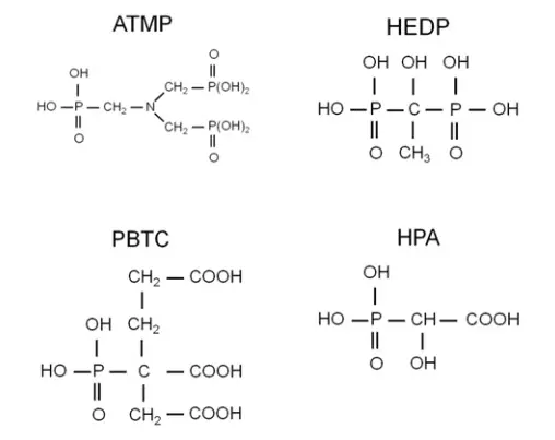
Figures 7.43a, b, c, and d. Amino trimethylene phosphonic acid; 1-hydroxyethylidene 1,1-diphosphonic acid; 2-phosphonobutane-1,2,4-tricarboxylic acid; hydroxyphosphonic acid
ATMP was the first phosphonate and was introduced in the early 1970s for calcium carbonate scale control. It served as a replacement for polyphosphates and could extend the saturation indices described earlier to:
ATMP exhibited fair to good corrosion inhibitor properties at the alkaline pH ranges of the (then new) phosphate-phosphonate programs. However, ATMP has a low tolerance for oxidizing biocides like chlorine, and it can also form calcium-phosphonate precipitates.
An improvement came with HEDP, which performs similarly to ATMP, but has a higher tolerance to oxidizers. HEDP replaced ATMP in most applications. Further research led to the development of PBTC, which has even higher tolerance for both chlorine and bromine than HEDP. Note the carboxylic acid groups (COOH) on this molecule, which revert to carboxylate (COO–) in alkaline solutions. Carboxylate is a key functional group for many of deposit-control dispersants. PBTC offers good corrosion protection, however, it is more expensive than other products.
HPA is a more recent addition to the organophosphate scale/corrosion inhibitor family, and it is particularly effective because it forms a monomolecular layer with calcium on metal surfaces.
Phosphonates are nearly always blended with other deposit control agents and corrosion inhibitors (mainly anodic). The normal phosphonate control range is 2 to 10 ppm (as PO4).
Development of polymers for crystal modification and sequestration have enhanced deposit control chemistry. Figure 7.44 illustrates various functional groups for important water treatment polymers.
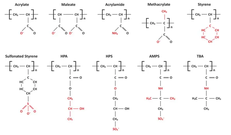
Figure 7.44. Functional groups on deposit control polymers. HPA, hydroxypropyl acrylate; HPS, 2-hydroxypropylsulfonate; AMPS: 2-acrylamido-2-methylpropane sulfonic acid; TBA, tert-butyl acrylate.
Along with the functional groups, polymer structure and size have an influence on scale inhibition. Molecules of 500–15,000 daltons in size are common, but in some cases much larger polymers may work well. Some polymers were designed to control calcium carbonate, calcium sulfate, and iron-related deposits, and others to control the calcium phosphates that can emerge from phosphate/phosphonate treatment programs.
Advanced formulations may include co-, ter-, and quad-polymers that have several different functional groups to treat complex waters. The compounds inhibit scale formation through several mechanisms, including sequestration, crystal modification, and crystal dispersion.
As can be observed in Figure 7.44, some of the compounds have the same functional groups, i.e., sulfonate and carboxylate, as those on ion exchange resins for makeup water treatment (see Chapter 3). For both applications, the negatively-charged active sites bind cations, including calcium and magnesium. The key difference is that solid ion exchange resins are contained within a vessel whereas the soluble and mobile deposit-control polymers move throughout the cooling water system. Common generic or trade names for these polymers include:
Some polymers modify or distort incipient crystals.
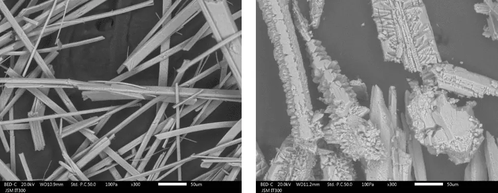
Figure 7.45a and b. Orderly and distorted growth of calcium carbonate crystals.
Distorted crystals exhibit none of the needle-like or flat-faced crystals shown in Figure 7.45a, rather the structure is much more fragile, friable, and does not form large crystal grains. PA, PMA, and similar compounds are effective for controlling calcium carbonate.
Calcium phosphate scale control is more difficult, especially on heat transfer surfaces. Scale prevention may require co- or ter-polymers that include sulfonate groups.
Iron presents a challenge to polymer chemistry, as iron binds strongly to carboxylic and sulfonate sites, reducing their effectiveness for calcium sequestration. In many waters, though, the iron concentration is low and does not present significant problems.
Polymeric dispersants are primarily negatively charged. Suspended particles usually also have an overall negative charge. The polymers enhance the negative charge, causing increased repulsion that keeps particles in suspension. Dispersion can be effective on finely-sized suspended solids such as silt, clay, and corrosion products, and possibly some microbiological debris. PAA and PMA are good products for dispersion.
Often, an important factor for deposit control is improving the ability of the polymers to penetrate deposits. This is especially true for organics, including oils and greases, as these compounds bind deposits together. Biofilm is also an especially strong binding agent. Surfactants can assist in breaking down these materials. Cationic, anionic, and nonionic compounds are all available.
Nonionic surfactants are similar to detergents by having a hydrophilic (water loving) functional group and a lipophilic (oil loving) chain. As the lipophilic end binds with oils, the hydrophilic end attaches to water molecules to remove the oil. Structural modifications to the lipophilic and hydrophobic active sites allow for specialized solvating chemistry.
Anionic surfactants serve for silt and suspended solids dispersion. Anionic surfactants sometimes produce foam, which is usually not a problem with nonionic compounds.
Cationic dispersants are primarily biodispersants or biocides. More details on these chemicals are provided in the microbiological control section of this chapter.
Where silt or macrofouling impacts heat exchanger performance, installation of backwash equipment may be beneficial, if the unit can come off-line periodically for cleaning.
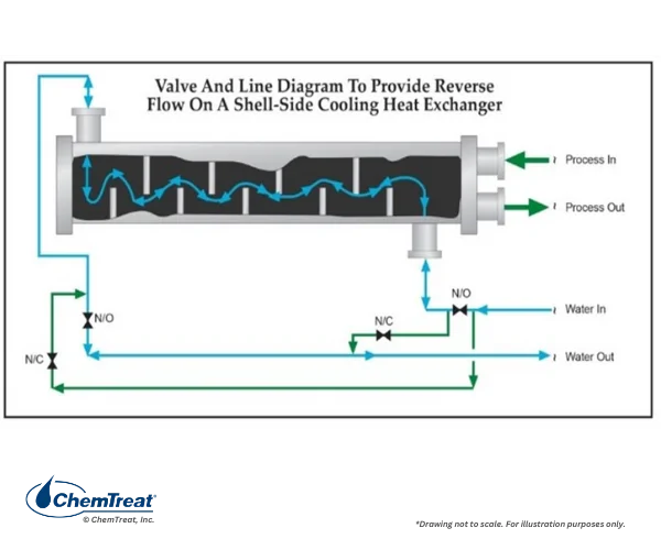
Figure 7.46a. Piping arrangement for reverse flow flushing.
An additional modification is to install a manifold below the heat exchanger to air bump the shell side water, as illustrated in the drawing below.
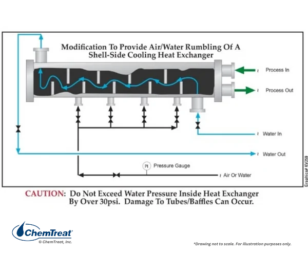
Figure 7.46b. Piping arrangement for air bumping.
Switching open-recirculating cooling water programs from acid-chromate to phosphate-phosphonate-polymer-zinc treatments allowed the new chemicals to also control corrosion.
Consider the basic diagram of the most common corrosion mechanism in cooling water systems, attack of carbon steel by dissolved oxygen. As a reminder, metal oxidation and loss occur at anodes, with electron transfer and reduction of dissolved species at cathodes.
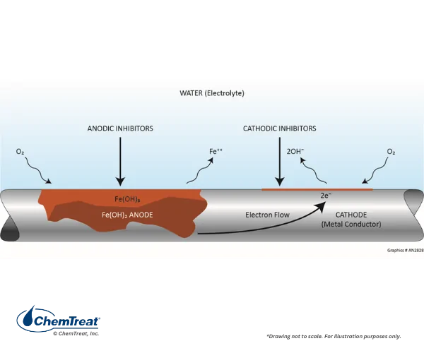
Figure 7.47. Basic corrosion diagram of carbon steel in oxygenated water.
Corrosion inhibitors effectively depolarize (reduce or stop the electrical flow) the corrosion reaction either at the anode or cathode, or both with blended inhibitor programs. In general, cathodic inhibitors precipitate at the locally high pH cathodic site to form a barrier that limits the rate of oxygen reduction. Anodic inhibitors typically promote the formation of a stable metal oxide at the anode surface. This limits metal dissolution. A considerable advancement has come with the development of film-forming products that protect the entire metal surface. Review of this filming technology follows the discussion below of traditional anodic and cathodic inhibition.
Table 7-3. Common Corrosion Inhibitors
| Anodic | Cathodic | Filming |
|---|---|---|
| Molybdate | Organic phosphates | Azoles (for copper alloys) |
| Nitrite | Ortho-phosphate | Filming Amines |
| Ortho-phosphate | Polyphosphates | Polysilicates |
| Zinc | RPSI* |
*RPSI stands for Reactive Polyhydroxy Starch Inhibitor. Details appear later in this chapter.
The earlier section on scale formation suggested that calcium carbonate is the most natural, and often most problematic deposit. However, when calcium and bicarbonate alkalinity concentrations exist in moderation, the presence of both can be beneficial. If the water has at least 50 ppm of calcium hardness and 50 ppm of alkalinity (both as CaCO3), the constituents potentially offer some corrosion protection as a cathodic inhibitor. The key is that at the cathodes shown in Figure 7.47, the production of hydroxyl ions generates a localized region of elevated pH. This can induce formation of a light layer of calcium carbonate that inhibits electron transfer at the cathodes.
As has been described, orthophosphate is a primary ingredient in phosphate-phosphonate programs to elevate the pH into a mildly alkaline range and minimize general corrosion. Additionally, orthophosphate reacts with iron (Fe2+) generated at anodes to form an iron-phosphate precipitate that deposits on the anodes and helps to inhibit the electrochemical reactions. Electron spectroscopy analyses have shown that the actual inhibitor layer is a gamma-iron complex with a formula of FeOOH•FePO4. The compound passivates anodes and stifles corrosion reactions. This monomolecular film breaks down over time, requiring a continuous phosphate concentration.
Orthophosphate can function as a cathodic inhibitor in specific environments. The elevated pH levels near the cathode may lead to the precipitation of calcium carbonate, zinc hydroxide, or calcium phosphate.
As noted, polyphosphate sequesters multivalent cations, like calcium and iron, to inhibit scaling. These complexes develop a net positive charge and migrate to cathodes to form a barrier deposit. The deposit blocks oxygen from the surface, reducing the corrosion current.
Zinc has been a standard additive to phosphate-phosphonate programs, with a common recommended concentration of 0.5–1.0 ppm. Zinc reacts with the hydroxyl ions produced at cathodes to form a zinc hydroxide (Zn(OH)2) precipitate that depolarizes cathodic reactions. Zinc can be effective against pitting corrosion. It has been a common practice to combine zinc with an anodic corrosion inhibitor such as orthophosphate for complete corrosion protection.
Many zinc compounds are highly insoluble, including zinc phosphate, and, if sulfide contaminants are present, zinc sulfide.
Of considerable and growing concern is phosphorus discharge to natural bodies of water, and the effects this discharge has on proliferation of toxic algae blooms.
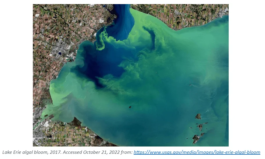
Figure 7.48. A landsat satellite image of Lake Erie during a harmful algae bloom event from September 2017.
At many locations now, phosphorus discharge is limited if not entirely banned. Metals discharge, including zinc and copper, is also restricted. These restrictions are a major factor in movement away from phosphorus-based programs to alternative film-forming programs.

As previously suggested, the key function of corrosion inhibitors is to protect metal surfaces. The former acid-chromate programs were excellent in this regard in that over time the chromate would react with the entire metal surface and establish continuity, as long as sufficient residual concentration was maintained in the cooling water. But the change to phosphate-phosphonate programs altered this methodology. Corrosion inhibition is largely accomplished by precipitation of solid products at cathodes and anodes. These deposits can be washed away, allowing localized corrosion. Conversely, overfeed may induce heavy precipitation of calcium phosphate and sometimes calcium phosphonates.
Based on several years of research, ChemTreat has developed a series of non-phosphate and non-zinc corrosion control programs (FlexPro®). These programs interact with metal surfaces to form a reactive polyhydroxy starch inhibitor (RPSI) complex that operates independently of calcium, pH, or other water chemistry components.3 The chemistry establishes a direct protective layer on metal surfaces, unlike the phosphate/phosphonate programs that rely on deposition of reaction products to form protective barriers, which, as has been noted, can be difficult to control.
A classic example of the need for improved corrosion protection methods is shown in the following illustration of a two-pass tube-and-shell heat exchanger, whose cooling water at the time was treated with a traditional phosphate-phosphonate program.
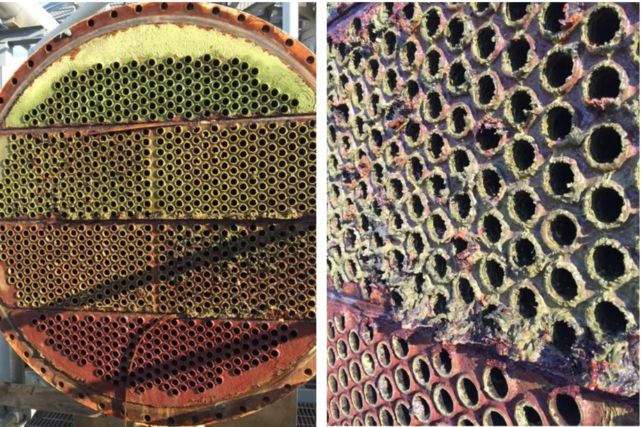
Figure 7.49. Two-pass heat exchanger on a phosphate-phosphonate program just prior to a change in treatment chemistry.
At the inlet end of the heat exchanger (the lower tubes of this unit), corrosion was problematic. At the warmer outlet side (the top half), deposition and scale formation were troublesome. Thus, the original program was not effective at mitigating corrosion or deposition depending on location. A switch to RPSI chemistry eliminated both issues.
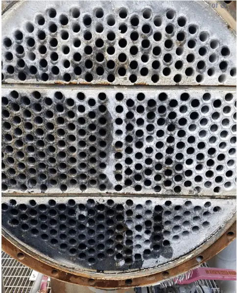
Figure 7.50. A similar heat exchanger on RPSI chemistry.
Primary cooling is an essential component of industrial operations, and disruptions can result in significant financial losses due to decreased efficiency and productivity. However, auxiliary closed cooling water systems, which play an essential role in supporting critical operations, are frequently overlooked. A failure within a closed system can result in a partial or full facility shutdown.
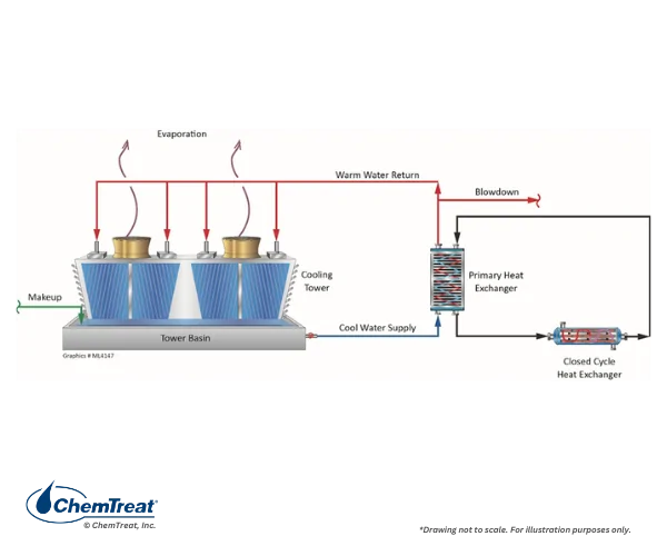
Figure 7.51. General schematic of a primary open-recirculating and secondary closed cooling system arrangement.
Tight chemistry control is an aspect that makes closed cooling effective for many applications, however, neglect of water treatment and monitoring can lead to corrosion and fouling.
The term “closed” cooling water system is somewhat of a misnomer, as virtually all systems experience leaks or small losses that require makeup. (If serious corrosion has occurred, these losses may be significant.) Systems are often designed with a head tank for makeup and to handle changes in demand. Some head tanks are open to the atmosphere, allowing oxygen to enter the cooling water and influence the corrosion potential.
Although water of differing qualities can potentially be used in CCW systems, condensate or demineralized water—specifically treated for this purpose—is typically preferred and serves as the primary focus of this discussion. Selection of condensate over less pure water minimizes the possibility of difficulties from scale-forming hardness compounds or corrosive agents such as chloride and sulfate. For systems that could potentially freeze during cold weather, a glycol solution may be required. This chemistry can obviously influence monitoring and dosage requirements.
Typical piping material for CCW systems is carbon steel, with stainless steel or perhaps copper alloys being a common choice for heat exchanger tubes, or plates in a plate-and-frame exchanger. Other metals may include aluminum or those metals contained in soldered fittings within heat exchanger cooling coils. When planning a treatment program, it is important to know the complete system metallurgy.
Two common corrosion inhibitors are nitrite and molybdate, as outlined below.
Nitrite (NO2‒), usually fed as sodium nitrite (NaNO2), is an anodic inhibitor by virtue of the chemical reaction with iron hydroxide at anodes. Sodium nitrite is an inexpensive and safe chemical to handle. As shown in the following reactions, nitrite promotes the formation of a passive iron oxide layer on the metal surface.
9Fe(OH)2 + NO2 → 3Fe3O4 + NH4 + 2OH + 6H2O | Eq. 7-24
9Fe(OH)2 + NO2 → 3(Fe2O3) + NH4 + 2OH + 3H2O | Eq. 7-25
Common is the addition of an alkalinity builder/buffering agent to maintain pH within a mildly alkaline range.
Anodic inhibitors like nitrite are also known as “dangerous” inhibitors, because if residuals fall below threshold limits, a small number of anodes will develop in a large cathodic environment. Rapid pitting may occur. Accordingly, a common recommended nitrite residual range is 500–1,000 ppm to inhibit general corrosion and pitting. However, when used with other inhibitors such as molybdate, lower nitrite residuals may be satisfactory. A concern with nitrite is that it is an excellent nutrient for bacteria. Nitrobactera agilis can grow rapidly by converting nitrite to nitrate. A classic example comes from an automobile assembly plant, where nitrifying bacteria plugged the small, serpentine cooling water tubes in automatic welders. Oxidizing biocides are not suitable for microbiological control, as the oxidizers convert nitrite to nitrate. A non-oxidizing biocide (see discussion later in this chapter) may provide effective control.
Sodium molybdate (Na2MoO4) was first used as a corrosion inhibitor in 1939 for automotive cooling systems. It appears that molybdate acts similarly to chromate and adsorbs onto the iron oxide matrix at anodes.
Fe2+ + MoO42- → FeMoO4↓ | Eq. 7-26
This layer then may further evolve into what is known as a gamma iron complex. Research shows that molybdate acts as a pitting inhibitor per its ability to accumulate within the acidic part of a pit and block the corrosion process. A common control range for molybdate is roughly 1/3 of nitrite. Although molybdate is an oxyanion, it requires some residual oxygen to be effective. Enough dissolved oxygen may enter through the cooling water makeup or head tank to provide the needed amount.
Molybdate is an expensive chemical, and costs may be prohibitive in some applications.
Copper is a superb metal for heat transfer, and copper alloys have been selected for many heat exchanger tubes. While copper is a more noble metal than iron, significant corrosion is possible in certain environments. As previously noted, the combination of dissolved oxygen and ammonia can be particularly corrosive. The most popular corrosion control methods for years have utilized azoles, in another example of film-forming chemistry. Figure 7.52 illustrates the general effect.
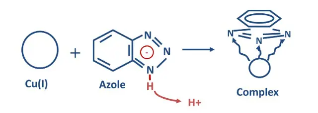
Figure 7.52. Illustration of copper alloy corrosion inhibition by azoles.
Azoles bond with copper atoms on the metal surface via an active nitrogen group. The plate-like organic ring then forms a barrier to protect the metal from the bulk fluid. The most common azoles are listed below.
1,2,3-Benzotriazole (BZT – C6H5N3) is the compound shown in Figure 7.52. It is the most fundamental azole but offers good corrosion inhibition in circulating cooling water systems.
Tolyltriazole (TTA – C7H7N₃) is similar to BZT but with a methyl group added to the organic ring.
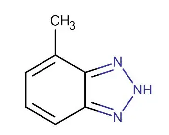
Figure 7.53. Structure of tolyltriazole.
The methyl group helps orient the molecule to establish a more uniform barrier film.
Another of the early azoles is 2-mercaptobenzothiazole (MBT), which has two sulfur groups in the nitrogen ring. One of the sulfur atoms also bonds with copper to form a thick passive film.
One difficulty with these original compounds is attack by oxidizing biocides, which, are necessary for microbiological control. Water treatment companies have developed halogen resistant azoles that contain additional side groups to resist oxidizer attack.
Recommended azole concentrations are usually maintained within a range of 1–10 ppm, and often 2–5 ppm.
In addition to bonding with the metal surface, azoles also form complexes with free copper ions in solution. So, dissolved copper contributes to the azole “demand,” which must be satisfied before surface filming can occur. However, if the azole is applied properly, any free copper should rapidly disappear and not normally be present thereafter. Azoles remain an important part of many FlexPro® programs.
The organic reducing agent diethylhydroxylamine (DEHA, (C2H5)2NOH)) is a metal passivator as well as an oxygen scavenger and may be used in closed systems. Most of the other reducing agents, including hydrazine, carbohydrazide, erythorbate and methylethylketoxime, are seldom utilized outside of boiler systems.
The iron passivation reaction by DEHA is as follows:
27Fe2O3 + (C2H5)2NOH → 18Fe3O4 + N2↑ + 4CH3COOH + 3H2O | Eq. 7-27
Advantages of organic passivators include that they contribute very little conductivity to the water, chemically reduce oxygen, buffer the water, and passivate the metal. This can be very important for some cooling processes that have extremely high heat flux and metal skin temperatures. In steel manufacturing for example; furnace hood, lance and electrodes are exposed to temperatures of over 3,000°F (1,650°C). Other industrial processes expose cooling equipment to very high electrical currents like automated welders in automotive assembly plants. High TDS water may cause electrical arcing and short circuits that damage equipment. Low TDS cooling water (≤500 µS/cm) is often required in such applications, a requirement that may be possible with organic passivators.
Some additional compounds may, in certain situations, serve as corrosion inhibitors. The next sections examine two of these.
Silicates
First used in 1921, sodium orthosilicate, or as the anion SiO32‒, is a precipitation type anodic corrosion inhibitor similar to orthophosphate. Silicates have been popular inhibitors in potable water systems, as they are non-toxic and occasionally find use for cooling water applications.
Orthosilicate technically is a mixture of silica monomers that coexist with polymerized silica, aka polysilicate (Figure 7.54). The percentage of poly vs. ortho compounds depends on the original silicate product, the concentration of the silicate in water, the pH and holding time.
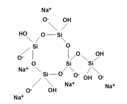
Figure 7.54. Polysilicate structure.
Orthosilicate is initially adsorbed onto anodes at the metal surface, where it reacts with iron to form a thin monomolecular layer.
Fe2+ + SiO32- + 2H2O → FeO∙Si(OH)3↓ + ½H2↑ | Eq 7-28
The layer blocks oxygen-metal contact and reduces corrosion. Eventually, the entire metal surface becomes covered, effectively isolating the metal from electrochemical reactions. Microscopic and x-ray examination of the silicate barrier indicates formation of two layers, with most of the silica in a surface layer adjacent to the water.
A common guideline is an initial silicate dosage to establish a 25-ppm residual above the background concentration. 30 to 60 days of operation at this level is typical. The concentration can then be reduced to 8–12 ppm above background for normal control. The film does not build on itself and will not form scale. However, treatment can be very problematic in open-recirculating systems or heat exchangers with high heat transfer because of the potential for magnesium or calcium silicate scale formation. Another potential foulant is aluminum silicate, which could result if alum is utilized as a coagulant for pretreatment clarification of the makeup water.
Borate
Sodium tetraborate pentahydrate (Na2B4O7•5H2O) is an anodic inhibitor that protects ferrous metals from corrosion. It appears that borate produces a ferric-borate layer on metal surfaces, encouraging the formation of ferric oxide which acts as a barrier to iron ion transport, particularly ferric ions, from the metal surface. As a relatively weak inhibitor, borate supplements other inhibitors like nitrite or silicate. A key feature of borates is a good buffering capacity at a mildly basic pH of 8.3 or slightly above.
Borates and boric acid can protect against various forms of wood degradation from fungi, however, the concentrations needed are much higher than those that can be reasonably maintained in recirculating cooling systems.
In some applications, methods are available to protect metals by either mechanical or electrical methods. This section looks at one of each, galvanizing from the materials side and use of sacrificial anodes from an electrical aspect.
Carbon steel galvanizing is common for many applications, including cooling tower structural components. Small galvanized cooling towers (see Figure 6.9 in the previous chapter) can often be ideal from a balance of structural stability versus cost standpoint.
Critical to long zinc life is proper conditioning of the galvanized coating to establish a protective dark gray zinc patina. This can be achieved by exposing galvanized components to the atmosphere for a period of several months. As previously shown in Figure 7.28, guard rails along roads and other zinc structures exposed to the atmosphere develop this patina naturally.
For cooling tower components that are installed without long-term atmospheric exposure, conditioning of the material for perhaps two months before the unit is placed in service is necessary to avoid the formation of “white rust.” Details of this chemistry are outlined later in the “Pre-Operational Cleaning and Passivation Section” of this chapter.
Sacrificial anode technology has been available for decades to protect pipes, tanks, condenser waterboxes, and other equipment. In these applications, a more reactive metal than steel, e.g., magnesium, aluminum, zinc, is coupled to the structure in strategic locations. When corrosion cells develop, electrons flow from the more reactive element through the connecting wires to the structure and cathodic sites on the steel. This leaves the steel intact at the expense of easily replaceable blocks of metal.
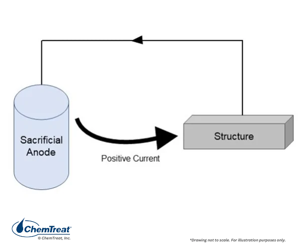
Figure 7.55. Basic diagram of a sacrificial anode. The metal dissolves releasing electrons that flow to cathodes.
A more sophisticated approach to the process is impressed current cathodic protection, wherein an external direct current power source is connected, or “impressed”, between the structure and the ground bed anodes.4 These systems are common on pipelines. Because the current is directly generated, less-reactive anodes than magnesium and aluminum are acceptable and may include low-alloy scrap steel.
Sacrificial and impressed current anode systems must be carefully designed, as they can be under- or over-specified. Too little current will allow the primary metal to corrode at localized anodes, while too much current can generate reactions at the metal surface that cause attack, e.g., hydrogen embrittlement. Further discussion is beyond the scope of this book.
Cooling water systems provide an ideal environment, warm and wet, for microbiological growth. Bacteria can form colonies in many locations, fungi will attack cooling tower wood, and algae will proliferate in sunlit areas, particularly on the decks and other exposed areas. More advanced microorganisms, such as amoeba and protozoa, often multiply in established microbial colonies. These more complex organisms can enhance growth of Legionella bacteria.
To control microorganisms, EPA-registered biocides, both oxidizing and non-oxidizing, are routinely employed, sometimes in conjunction with a biopenetrant/biodispersant. This section discusses the common microbes that flourish in industrial water systems, and it outlines control strategies.
Bacteria consist of single-celled prokaryotes (microbes that lack a defined cellular nucleus) and may be as small as 0.1 microns. Bacteria can be classified into five groups according to their basic shapes: spherical (cocci), rod (bacilli), spiral (spirilla), comma (vibrios) or corkscrew (spirochaetes). They can exist as single cells, in pairs, chains, or clusters. Shape alone, however, is not a good indicator of a bacterial type because a single strain of bacteria can take on different shapes depending on growth conditions. Different species may have similar morphologies.
Bacteria have a wide range of nutrient, oxygen, and energy needs. Aerobic bacteria require oxygen, whereas anaerobic bacteria thrive without oxygen. Facultative anaerobes are microbes that produce energy by aerobic respiration if oxygen is present, but can switch to a fermentation process if oxygen is absent. Bacteria are categorized as either planktonic (free floating) in the bulk water or sessile in colonies attached to surfaces. Sessile microbes are responsible for biofilms and are usually the primary concern when it comes to impact on water system performance.
Bacteria are also grouped by optimum temperature ranges for growth; thermophilic bacteria, above 122o F (50°C), mesophiles within a range of 68–99° F (20–37°C), and psychrophiles at 39–50°F (4–10°C). Microbes that can grow and thrive in extreme environments are called extremophiles, and while each species of bacteria grows best within an optimum temperature range, most can also adapt and grow at temperatures outside the optimum range.
In most modern industrial cooling water systems, pH is maintained in an alkaline range for corrosion control, and this is ideal for bacterial growth. The most common bacteria are those of the Pseudomonas genus, but other species include:

Figure 7.56. Pseudomonas aeruginosa.
When colonies develop, aerobes, anaerobes, and facultative organisms will usually become established within the biomass.
The term fungi includes both yeasts and mold. Fungi are a group of non-photosynthetic eukaryotic organisms that are larger in size than bacteria. Most fungi are aerobic and require oxygen for survival. Yeast, such as those for beer or winemaking, are facultative anaerobes. Fungi are important organisms for many waste treatment processes as they break down organic material. In industrial cooling water systems, these attributes can be harmful. The fungi Basidiomycetes and Ascomycetes can attack cooling tower wood.
Whereas yeast is a type of fungi that contains only single cells, molds contain multiple identical nuclei. The colonies are characterized by threadlike, multi-cellular (and sometimes colorful) filaments called hyphae. Molds are important industrially for production of antibiotics and cheese.
Fungi thrive in acidic environments and are less active in modern cooling water systems per typical operation within a mildly basic pH range. However, it is not uncommon to find fungi in biofilm deposits, which is suggestive of an acidic environment within the biofilm.
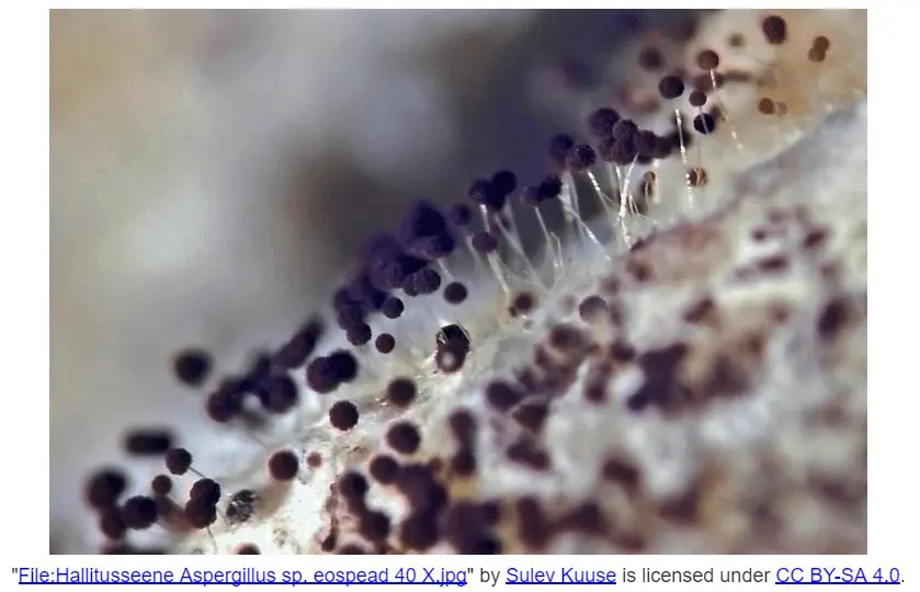
Figure 7.57. Filamentous fungi.
Algae are a diverse group of photosynthetic aquatic organisms that require sunlight. Algae are photoautotrophs, meaning that they can produce many needed nutrients from carbon dioxide, water, and sunlight. Phosphate is an additional critical nutrient and is a limiting factor in growth.
In open recirculating cooling systems, algae grows in those areas exposed to the sun, most notably the decks of crossflow towers. Many of these towers have covered decks to block sunlight, thereby limiting the opportunities for algal growth. Left unchecked, algal fouling can lead to unbalanced water flow in the cooling tower and reduced operating efficiency. Algae can appear in other sunlit areas, however.
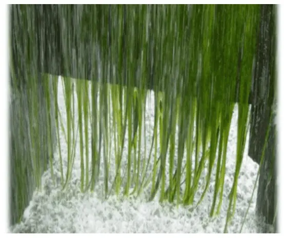
Figure 7.58. Extreme algae growth on the side of a cooling tower.
As previously noted, microbes in cooling water are either free-floating or sessile. System conditions will in some measure dictate sessile development. For example, high-velocities may physically prevent microbes from settling. When microbes attach to surfaces, some organisms almost immediately begin to produce a protective, polysaccharide layer commonly termed biofilm or slime. Aerobes usually thrive in the outer layers of the biofilm (near the bulk fluid) while the anaerobes grow in areas of low oxygen concentration, i.e., at the base of the biofilm. The slime entraps other microorganisms, silt, corrosion products, and additional debris in industrial waters.
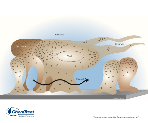
Figure 7.59. Biofilm structure.
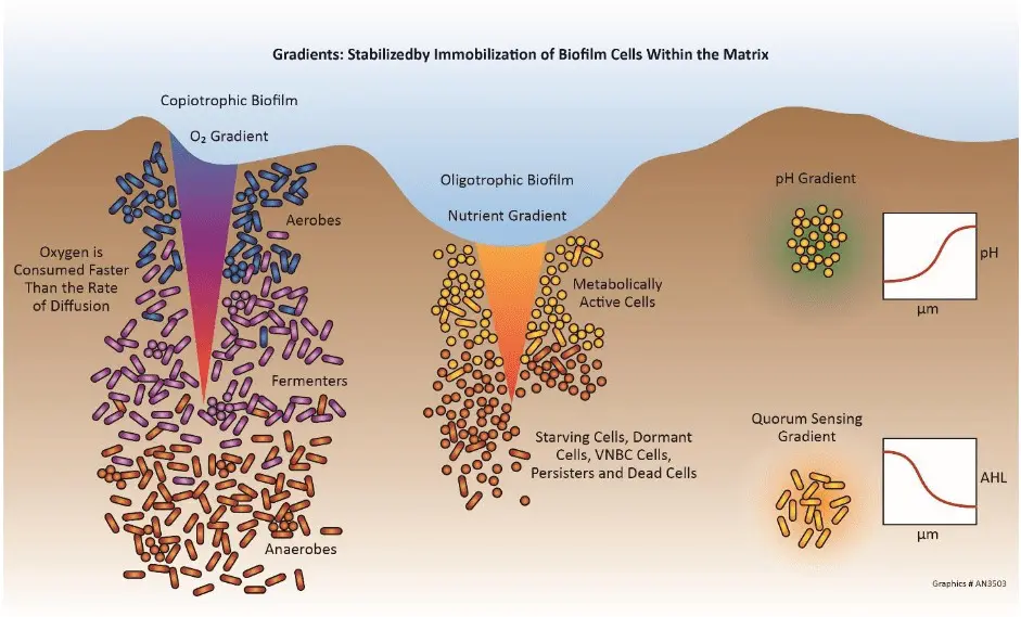
Figure 7.60. Nutrient gradients in biofilm.
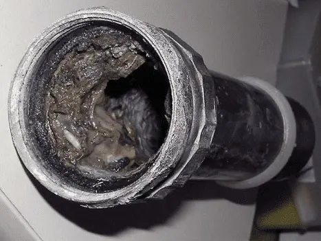
Figure 7.61. Bioslime. Photo credit: CBE-MSU Bozeman.
The protective biofilm makes sessile microorganisms more difficult to kill than planktonic microbes. Research performed by Professor Phil Stewart at Montana State University has shown that the movement of any molecule into a biofilm is limited by diffusion and reactivity. Thus, the extent of biocide penetration is limited by the reactivity of the molecule towards the protective slime. We will examine these concepts shortly. Ideally, a plant’s cooling/service water biocide feed system has been designed and is properly operated to kill planktonic organisms before they can establish colonies. However, many times the plant staff must deal with treatment of well-established colonies.
Higher Life Forms – Amoeba and Protozoa
As previously noted, if microbiological colonies become well established, higher life forms often emerge. Amoeba and protozoa are ubiquitous single-celled eukaryotic microbes. The protozoan cell may have specialized appendages such as cilia or flagella for motion.
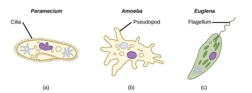
Figure 7.62. Images of higher microbial life forms.
While many types of amoeba can cause human health problems, the relationship between amoeba, protozoa, and Legionella bacteria is well known. Legionella is the organism first discovered in 1976 when it infected people attending an American Legion convention in Philadelphia. Nearly three dozen people died, and many more became ill. It was traced to water vapor containing the bacteria in the exhaust plume of a cooling tower on the roof of the convention hotel. The vapor entered the intake of an air handling unit and spread through the hotel.
The link between Legionella and amoebae was first demonstrated by Tim Rowbotham, who showed that amoebae could serve as hosts for the Legionella. Soon after, Kurtz described the isolation of amoebae in cooling waters which contain Legionella, thereby lending further support to Rowbotham’s theory on the relationship between the two. A later report by Rowbotham then offered a mechanism for the growth and proliferation of Legionella within the amoebae species, Acanthamoeba polyphaga.
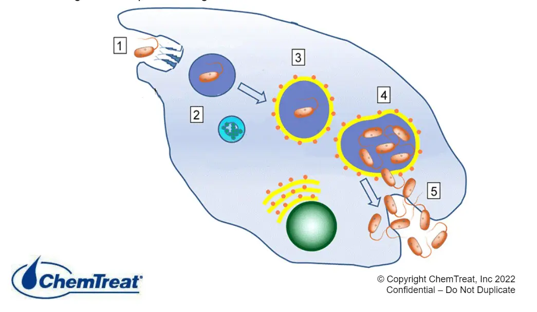
Figure 7.63. Amoeba/protozoa with Legionella inside.
Studies have found that Legionella can grow in and be released from higher organisms; however, effective design and operation of the biocide feed system is essential to reduce microbiological fouling. Another important measure is finding and eliminating all dead leg piping. Stagnant water can allow organisms to proliferate.
Amoeba and protozoa are much more resistant to the biocidal effects of halogens than the simpler microorganisms but are susceptible to several commonly used non-oxidizing biocides.
Fouling of surfaces by organisms larger than bacteria or fungi is considered macrofouling. Common organisms are mussels, clams, and barnacles.
Fresh water clams first became problematic in the United States in the late 1970s when the Asiatic clam, Corbicula flominea, entered the country. Around 1986, Dreissena polymorpha, the zebra mussel, was introduced into the Great Lakes. These mussels are native to the Black and Caspian Sea area and can achieve densities of up to 700,000 individuals per square meter.
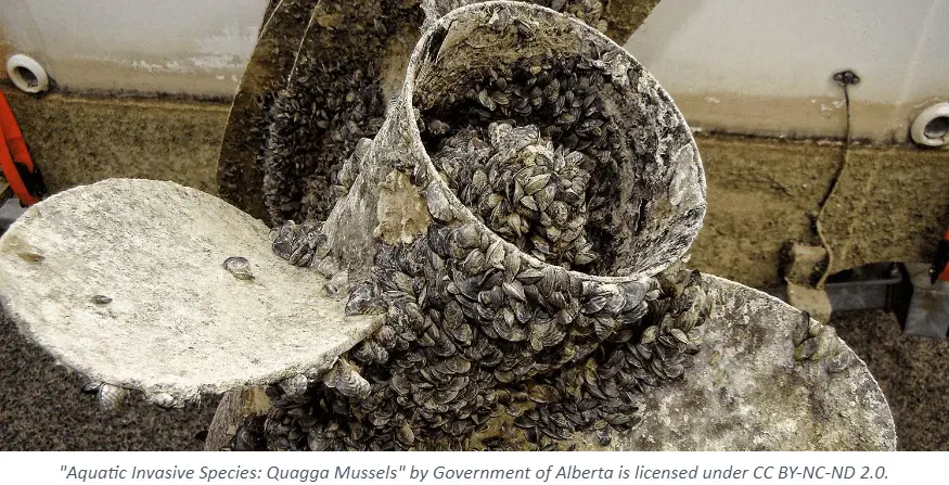
Figure 7.64. Quagga mussel fouling of cooling water equipment. Note how mussels will attach to each other as well as equipment surfaces.
Both organisms present significant challenges to water intakes and systems, but zebra mussels have been the primary focus in recent years following their spread from the Great Lakes through various waterways in the eastern and midwestern United States.
As a preliminary note to the following discussion of cooling water biocides, many countries, including the United States, Canada, and Mexico, have placed limits on the use of antimicrobial compounds in industrial settings. Product registration is required, which typically comes with limitations on how and where the product may be applied. Products with the same type and level of active components but with different trade names each require registration as separate entities. In the United States, registrations fall under the jurisdiction of the Environmental Protection Agency (EPA) and the Federal Insecticide, Fungicide, and Rodenticide Act (FIFRA).
In addition to federal registration, additional state/territory/province regulations may be placed on the use of antimicrobial products. Most companies – especially larger facilities – also require finalized processes before a new chemical can be applied. Plants also must comply with discharge limits for some compounds. In the U.S., these regulations are under the auspices of the National Pollution Discharge Elimination System (NPDES) created within the Clean Water Act (CWA) of 1972. The regulations require approved permits before a water stream with treatment chemicals, including biocides, can be discharged to the environment. Individual states must enforce the NPDES regulations but are free to impose more stringent guidelines if desired.
For the vast majority of recirculating and once-through cooling waters, oxidizing biocides are the backbone of microbial control program, as the chemistry usually represents the most cost-effective method for maintaining system cleanliness. Harder to treat systems may also benefit from a supplemental non-oxidizing biocide, and/or the addition of a biopenetrant/biodispersant. The most common compounds in each category are discussed below.
It has been suggested that 1893 was the first year in which chlorine was first applied as a drinking water biocide, with rapid development of the technology in the early 1900s.
Chlorine gas was the workhorse for drinking water and then cooling water treatment for many years. One-ton cylinders became the method of storage at many facilities, drinking water and otherwise. When chlorine is added to water the following reaction occurs:
Cl2 + H2O ⇌ HOCl + HCl | Eq. 7-29
HOCl, hypochlorous acid, is the killing agent, and it functions by penetrating cell walls and then oxidizing internal cell components. The efficacy and killing power of this compound are greatly influenced by pH because of the equilibrium nature of HOCl in water, as shown below.
xHOCl ⇌ H+ + OCl- | Eq. 7-30x
OCl– is a much weaker biocide than HOCl, probably because the charge on the OCl- ion does not allow it to effectively penetrate cell walls. The dissociation of hypochlorous acid dramatically increases in relation to rising pH.
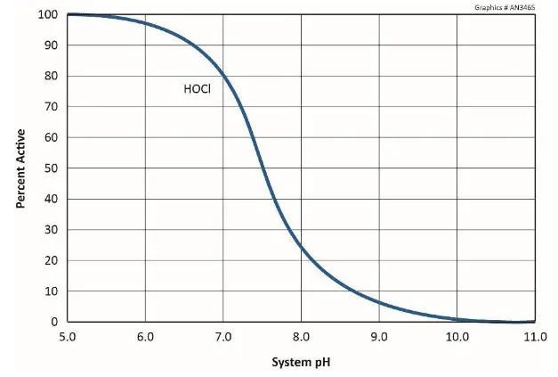
Figure 7.65. HOCl dissociation as a function of pH.
Because many cooling tower scale/corrosion treatment programs operate at an alkaline pH, often near or slightly above 8.0, straight chlorine chemistry may not be the best choice.
Due to safety issues with gaseous chlorine, many industrial facilities switched to liquid sodium hypochlorite (NaOCl, aka bleach), with a common active chlorine concentration of 12.5%. Bleach often contains a small amount of sodium hydroxide, so when it is injected into the cooling water stream, it slightly raises the pH. However, if the water is alkaline to begin with, most of the reactant will exist as the OCl– ion. An alternative is on-site hypochlorite generation, which has proven to be effective in some applications.
Chlorine Demand
As a strong oxidizer, hypochlorous acid can react with compounds that are often present in recirculating cooling and process waters. The most prominent are ammonia and organics. The sum of these non-antimicrobial reactions is referred to as “chlorine demand.” The reactions consume biocide and lower the concentration available to attack microbes. Some reactions can also produce halogenated organics, whose discharge concentration may be regulated.
Chlorine Alternatives
As has been noted, the killing power of chlorine declines with rising in pH. A popular answer to this difficulty has been bromine chemistry, where a chlorine oxidizer (bleach is the common choice) and sodium bromide (NaBr) are blended in a slipstream and injected into the cooling water. The reaction produces hypobromous acid (HOBr), which has similar killing powers to HOCl, but functions more effectively at alkaline pH.
HOCl + NaBr ⇌ HOBr + NaCl | Eq. 7-31
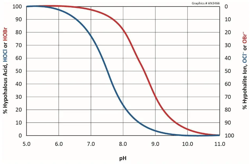
Figure 7.66 Comparison of HOCl and HOBr dissociation.
Like hypochlorous acid, hypobromous acid is a strong oxidizer that also has a halogen demand. However, unlike chlorine which reacts irreversibly with ammonia, the bromine-ammonia reaction is reversible, leaving bromine free for activity towards microbes.
Halogen Stabilizers
Several chemical compounds are available that can stabilize chlorine and bromine and then release the oxidizers gradually, and where they are most needed. The stabilized halogen typically exhibits a lower oxidizing power when compared with the parent halogen, but this reduced oxidizing offers benefits with respect to microbial control by reducing undesirable reactions with the protective slime.
Three classes of stabilizers dominate the market: sulfamate, dimethylhydantoin, and isocyanurates.
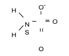
Figure 7.67. Sulfamate molecular structure.
Sulfamate-stabilized halogens are perhaps the most common compounds of this type. They are available in liquid form and are primarily offered as mixtures of both bromine and chlorine species.
Stabilized chlorine and bromine dimethylhydantoin species are another option.
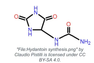
Figure 7.68. Basic hydantoin structure.
These compounds are available as tablets/pucks, granules, and powders. Each product has individual dissolution characteristics, which requires careful evaluation when selecting a feed system. A common design for feeding solid products is a small vessel in which the tablets/pucks can be loaded, then gradually dissolve in a cooling water slipstream that returns to the main system. Liquid systems that produce stabilized hydantoin on demand via the reaction of sodium hypochlorite with liquid dimethylhydantoin are another common design.
Rounding out the trio of stabilized halogen classes are the isocyanurates, available principally as solids. The solid formulations are quite stable, allowing a long shelf-life.
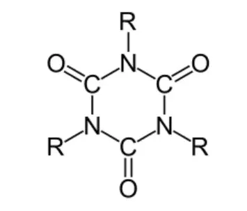
Figure 7.69. General isocyanurate structure. “R” represents an organic, usually short-chain, molecule.
Many of the same limitations for chlorine and bromine exist for stabilized halogens. The products should first be blended with water, and not directly with other chemicals that could cause contamination or adverse reactions. Liquid product formulations often introduce some causticity to the water.
Chlorine Dioxide
Chlorine dioxide (ClO2) is a gas at room temperature that is stable and soluble in water to a maximum concentration of approximately 3,000 ppm. It must be prepared on site via the reaction of either sodium chlorite (NaClO2) or sodium chlorate (NaClO3) with an additional oxidizing agent under acidic conditions. Chlorine dioxide is more expensive than the halogens, but modern production techniques have lowered the cost.
The oxidation state of chlorine in the ClO2 molecule is +4, making it quite reactive to many compounds. However, chlorine dioxide exhibits a high degree of reaction selectivity, and it can penetrate biofilms to attack microbes. The selectivity is advantageous for other water treatment applications, including wastewater phenol destruction and odor control.
Because chlorine dioxide exists as a gas in solution, it is easily stripped by aeration. ClO2 should be introduced below the surface of receiving waters to minimize losses. Handling of the chemical precursors for chlorine dioxide, which may include sulfuric acid, requires attention to safety, although modern ClO2 generators are typically designed with safety in mind. Strict adherence to operational guidelines is important.
Chloramines
Chloramines have been used for microbial control in industrial water systems for over a century. In water containing ammonia, continued chlorine feed will produce a series of chloramines, starting from monochloramine (NH2Cl), then dichloramine (NHCl2), and finally nitrogen trichloride (NCl3). The solution reaches “breakpoint” once all ammonia has been consumed, upon which free chlorine appears.
Monochloramine is the compound of interest for modern biofouling control, and technologies are now available to produce a pristine stream of NH2Cl for this purpose. When compared with sodium hypochlorite, monochloramine is less reactive but almost equivalently toxic. The reduced reactivity allows it to penetrate biofilms and attack underlying organisms. However, monochloramine generally needs a longer contact time than hypochlorite to achieve the desired microbial destruction.
Peroxide Oxidants: Hydrogen Peroxide, Peracetic Acid, Percarbonic Acid
Several peroxide-based biocides/disinfectants are on the market, and all can produce the peroxide radical (OH∙) as the reactive compound. The most common products are hydrogen peroxide, peracetic acid, and percarbonic acid.
Unlike chlorine dioxide, peroxides react indiscriminately with a wide array of compounds, including microbes. Reaction occurs at the cell wall, and the damage causes cell lysis and death. Unlike halogens, oxygen is the byproduct of reactions or auto-decomposition of the biocide. An additional advantage is that the oxygen release can transform the water from anaerobic to aerobic conditions.
A disadvantage of peroxide-based biocides/disinfectants is the potential for deactivation from catalase-producing microbes. Catalase is an enzyme that all living cells produce for protection from hydrogen peroxide generated metabolically. However, some microbes produce large quantities of this enzyme and increase production when high levels of H2O2 are present. This renders the long-term use of peroxide as a disinfectant problematic. However, for periodic off-line cleaning, peroxide is extremely effective at removing biofilms and other organic-based deposits, especially when used in combination with caustic, a surfactant, and at warm temperatures.
While oxidizing chemicals normally serve as the foundation of cooling water biocide programs, microorganisms can develop partial immunity, largely from the protective biofilms. Accordingly, in some applications feed of a non-oxidizing biocide on a periodic basis, e.g., once or twice per week for an hour or so, can help to control microbial growth. Whereas oxidizing biocides typically damage cell walls, the non-oxidizers penetrate cell walls to then react with compounds within the cell that are necessary for life. The following sections examine several of the most common non-oxidizers.
Bronopol
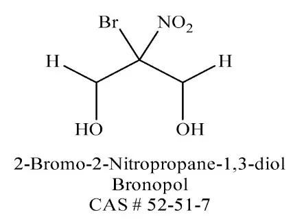
Figure 7.70. Structure of bronopol.
Bronopol is a halogenated diol that contains an electrophilic carbon atom. It is used extensively in water treatment applications and, like 2,2-dibromo-3-nitrilopropionamide below, has seen limited applications in the oilfield. Bronopol is particularly effective against Pseudomonas bacteria. The compound seems to function via different chemical mechanisms depending on whether conditions are aerobic or anaerobic. Bronopol is not a fast-acting biocide. The compound may release formaldehyde upon decomposition, but the formaldehyde is not responsible for its biocidal properties.
Bronopol will hydrolyze in aqueous solutions at varying rates depending on pH. The hydrolysis rate is much faster at alkaline pH. Increasing temperature increases the rate of hydrolysis at a given pH. The optimum pH range for bronopol efficacy is 5–9. The compound will react with and become deactivated by sulfides and bisulfite-based oxygen scavengers. Lastly, bronopol possesses the potential to release nitrite that, in the presence of secondary amines, can form nitrosoamines.
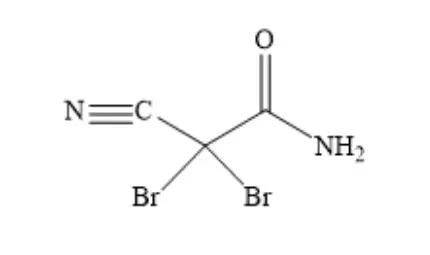
2,2-dibromo-3-nitrilopropionamide (DBNPA)
Figure 7.71. Structure of DBNPA
DBNPA is a halogenated amide that is widely used in water treatment and pulp and paper applications. In the oil field, DBNPA serves to treat makeup water for fracturing fluids. DBNPA’s biocidal action is very rapid, and residual concentrations quickly hydrolyze to less toxic by-products. Rapid hydrolysis can be advantageous if the wastewater stream discharges through a retention pond, allowing the residual to decompose without need for a deactivation chemical. DBNPA has proven to be effective in controlling microbiological fouling in high-purity makeup water systems, particularly reverse osmosis units.
The presence of two bromine atoms at the second carbon of DBNPA makes the site very electrophilic, which then reacts with the nucleophilic, sulfur-containing amino acids methionine and cysteine in microbial cells. The reaction is irreversible and the result is inactivation of the protein that contains these amino acids. Cell death ensues.
The optimum pH range for maximum DBNPA efficacy is 4.0–8.0. The hydrolysis rate increases with increasing pH, and the compound rapidly loses potency above 8.0 pH. Hydrolysis also increases with rising temperatures. DBNPA is deactivated by sulfides and bisulfite-based oxygen scavengers. The compound is not stable to UV light, and it reacts with ammonia.
Glutaraldehyde
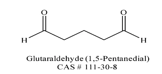
Figure 7.72. Structure of glutaraldehyde.
Glutaraldehyde has been used extensively in industrial water treatment applications, including oil and gas operations, the paper industry, and for medical instrument sterilization. The chemical reacts with two of the twenty essential amino acids, lysine and arginine, necessary for cell function. Efficacy is optimal within a pH range of 7–10, but the compound is more stable at an acidic pH. Glutaraldehyde will react with bisulfite-based oxygen scavengers to form an aldehyde-bisulfite addition product. This reaction is reversible and at elevated temperatures (>60°C), the complex will break down to release the glutaraldehyde. The reaction of glutaraldehyde with amines or ammonium ions is not reversible and produces a byproduct with little to no biocidal efficacy.
Isothiazolones
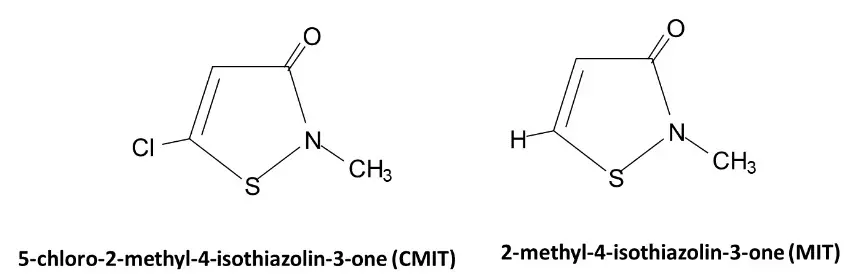
Figure 7.73a and b. The two common isothiazolones for cooling water treatment.
Apart from cooling water applications, formulations of isothiazoline are, in very slight concentrations, a common anti-microbial agent in many detergents. The most common isothiazolone-based biocidal formulation for cooling water treatment has a 3:1 mixture of CMIT and MIT. The CMIT and MIT concentrations in registered products are either 1.5 percent or 4 percent active ingredient. Various stabilizers are part of industrial formations, including cupric nitrate, magnesium nitrate, and potassium iodate. Also available is a 1.5 percent active product stabilized with bronopol. Proper product selection is often influenced by the stabilizer. The isothiazolones are broad spectrum but slow-acting bactericides that also show good reactivity towards fungi.
Both CMIT and MIT are incompatible with hydrogen sulfide, or other sulfur-based nucleophiles. Therefore, if sulfur-reducing bacteria (SRB) are present, isothiazolones may not be the best non-oxidizer choice. Elevated pH (>9.5) will reduce CMIT, but MIT is stable at a pH above 10.0. Isothiazolones can be deactivated with sodium bisulfite at a 2:1 mole ratio to isothiazolone.
Quaternary Amines
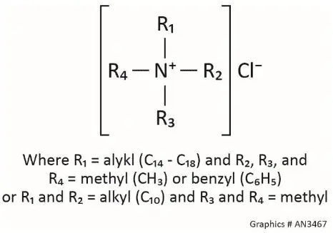
Figure 7.74. General structure of quaternary amines.
Quaternary amines, or “quats” as they are commonly termed, have been utilized extensively in a wide variety of cooling and process water applications. The molecules are positively-charged, with four alkyl groups attached to a central nitrogen atom. One or more of the alkyl groups consists of a methyl, benzyl, decyl (C10), coco (C14), or soya (C18) chain. Quats are commonly fed in combination with other biocides and are usually very cost effective. Some compounds also serve as filming-amine corrosion inhibitors.
Quats have surfactant properties that solubilize cell membranes, leading to cell damage and death. The compounds are especially effective when used in combination with other biocides that also attack cell walls.
Foaming is a concern with quaternary amines. The alkyldimethylbenzyl ammonium chloride (ADBAC) quat foams extensively, but low-foaming compounds such as didecyldimethyl ammonium chloride (DDAC) are now available. Foaming may be problematic in seawater systems where the foam can interfere with the operation of deaeration towers. The surfactant properties of quats can inhibit the separation of oil/water emulsions in oilfield production systems. Hard water can decrease the biocidal activity of quats, and quats can react with negatively-charged scale and corrosion inhibitors, which lowers efficacy.
Tetrakishydroxymethyl phosphonium sulfate (THPS)
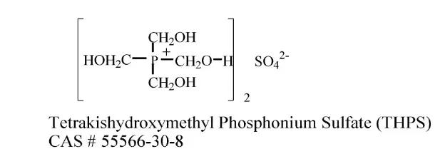
Figure 7.75. Structure of THPS.
THPS is employed mostly in oil-field applications but has also been used in traditional water treatment systems, as well as some non-biocidal applications. THPS is unique in that it will kill microorganisms, reduce hydrogen sulfide concentrations, and react with and dissolve iron sulfide.
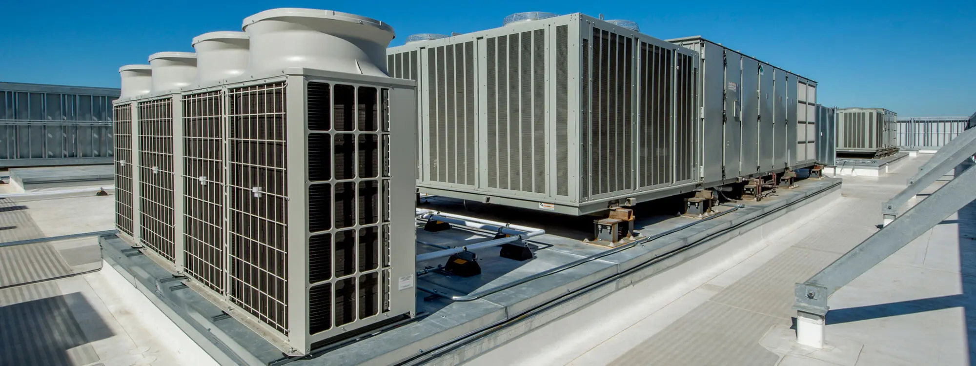
The evolution of high-efficiency cooling tower film fill led to significant improvement in tower performance. However, as already has been noted, with the increased surface area of high-efficiency fill comes increased potential for scale formation and fouling. The best method to clean tower fill depends on several factors, including safety concerns, system metallurgy, in-service vs. out-of-service cleaning, potential impact on plant operations, disposal options for the cleaning solution, impact on the environment, and the chemical and physical nature of the foulant.
Hard mineral deposits most commonly consist of silica/silicates or calcium carbonate (calcite). Silica solubility is proportional to temperature, and deposits often form near the bottom of counter-flow fill pack where the cooling water temperature is lowest, dissolved solids are most concentrated, and uneven water/air distribution can lead to dry spots. Higher temperature water at the top of the fill has the lowest calcite solubility and promotes faster deposition kinetics. However, as the water passes through the fill, the minerals are concentrated slightly by evaporation, and the pH will rise slightly as excess CO2 is stripped.
Applying specialty surfactants that penetrate the deposits and induce spalling from the slightly flexible plastic substrate is one technique that can be effective on hard scale in early stages of deposition. The surfactant is typically applied with the normal scale inhibitor program for an extended period of 60-180 days. Treatment may remove up to 70–80% of the deposits. Prior to cleaning, it is imperative to identify and correct the scale-forming conditions.
For large cooling systems, where the predominant scale is calcite, the fill can be cleaned over time by reducing the operating pH and/or cycles of concentration until the water is below calcite saturation. Calcite often serves as the binder for the deposit matrix, so calcium carbonate dissolution can often be quite effective in breaking apart the entire deposit. Sulfuric acid is an obvious choice for systems that already have it for pH control. Less corrosive compounds include organic acids or inhibited sulfamic acid. Some organic acids are more effective than mineral acids at intermediate pH and are synergistic with sulfuric acid. At pH 5.0, application of an appropriate organic acid will accelerate the rate of calcite dissolution by 10–20x as compared to sulfuric acid alone.
For predominantly light calcium carbonate scaling, off-line acid foam cleaning has been successfully employed, at least on smaller cooling towers. When applied by skilled specialists at the top of the fill, the slow passage of foam through the fill provides extended time for the acid to contact scale. The relatively low volume of spent and mostly neutralized foam cleaning solution can potentially be collected in the sump for disposal or perhaps be blended with circulating water from neighboring in-service tower cells. This blending is subject to plant safety and environmental requirements.
Mineral scales can also be mechanically removed, to some extent, either in situ or ex situ. Per the scale’s brittle nature relative to the flexible PVC fill material, some deposits can typically be dislodged by mechanical cleaning from below.
Deposits where microbes or organics serve as the binder for the deposit matrix are characterized by a soft, often mud-like consistency. Unlike mineral scales, microbiological deposits tend to accumulate primarily in the middle of the fill. Water velocities directly under the spray nozzles are generally high enough to inhibit microbial adhesion in the upper layer. For this reason, microbiological fouling sometimes goes undetected because it is not visible from above. As the water velocity slows within the fill, microorganisms begin to colonize fill surfaces, acting as a filter for suspended solids. Fouling tends to be more intense in the middle than at the bottom because the last few inches of fill do not physically support a thick, soft deposit. The inability to clearly view microbiological deposition from either top or bottom, combined with the difficulty of inspecting the middle fill layers, often allows fouling to progress undetected until it has reached an advanced stage. Several techniques have been devised to monitor susceptible areas, including suspension of fill sections from load cells; cutting an access window into the tower casing to allow a middle section to be removed periodically for inspection; suspending a fill section beneath the main fill to allow it to be easily inspected and weighed. Each method has been partially successful, but none have proven to be totally satisfactory.
Several methods exist to remove biological-silt deposits from cooling tower fill. Hyperhalogenation is a common technique, but results are often disappointing. Potential corrosion of system components and the need to dechlorinate prior to discharge are additional important issues when considering this method.
Microbiological deposits typically have high water content and will shrink and detach from surfaces when thoroughly dried. However, effectively drying out cooling tower fill can prove problematic even with the help of fans and if the tower is located in a low humidity climate. Chlorine dioxide has also been used as a cleaner for cooling tower biofilms with some success. The most widely practiced and effective cleaning method for deposits with microbiological or organic binders is hydrogen peroxide (H2O2) because of its oxidizing strength and the physical action of the oxygen micro-bubbles produced as it reacts with organic deposits. The positive environmental aspects of hydrogen peroxide from the rapid breakdown to water and oxygen, and its ease of application are additional factors favoring peroxide as a fill cleaner. Typical dosages are in the range of 500–3,000 ppm active H2O2. Surfactant addition in low concentrations will help loosen deposits. Polymeric dispersants are often included to keep solids in suspension for wastewater discharge. Disposal procedures should be well-established to deal with discharge of these typically turbid waters.
Figures 7.76 a and b below illustrate the appearance of slime-silt deposits on moderately fouled high efficiency cooling tower fill before and after cleaning.

Figure 7.76a. Cross-fluted tower fill fouled with a slime-silt deposits prior to peroxide cleaning

Figure 7.76b. Cross-fluted tower fill after peroxide cleaning.
In cases where the deposit contains a high percentage of inorganics, the circulating water may become highly turbid. The project procedures should include provisions for disposal of the turbid wastewater following the cleaning process.
In cases where biofouling of a cooling tower or heat exchanger does not require an off-line cleaning, supplemental biodispersant feed with the biocide(s) may be sufficient to keep the equipment clean and maintain clean conditions.
An effective biodispersant with its surfactant properties can help to prevent microbial attachment to surfaces or facilitate the removal of deposits. Several types of surfactants are available, including anionic alkylbenzene sulfonates, alkyl polyglycosides, and nonionic ethylene oxide/propylene oxide (EO/PO) polymers.
Anionic compounds that prevent agglomeration of smaller particles by absorbing onto particle surfaces, increasing the negative surface charge and particle repulsion, are most common. Because these dispersants have a negative charge, they may interact with cationic species in the water (especially calcium in highly-cycled cooling towers) and lose effectiveness.
Biodetergents are typically nonionic molecules that will not react with other water treatment compounds. They exhibit good efficiency in hard waters and are stable compounds.
The role of the dispersant is not to kill microbes but to assist in removing deposits. The initial dispersant concentration is dependent upon the extent of existing colonies and will be higher than subsequent maintenance dosages. The dispersant should be injected prior to the biocide treatment, so that it can condition the biofilms and increase the efficacy of the killing agent(s). As with any surfactant, the potential for foaming exists, so procedures should be in place to combat foaming issues. Also, the choice of dispersant may be influenced by the environmental toxicity of the chemical and potential regulation in the discharge permit.
While traditional water treatment programs rely on various chemistries to control scale, corrosion, and microbiological fouling in industrial water systems; some companies market non-chemical technologies as green or environmentally-friendly alternatives. Examples include magnetic devices, pulsed-power systems, electrostatic systems, ultrasonic instruments, and hydrodynamic cavitation systems. Manufacturers claim that the devices can replace traditional chemical treatments.
At first, these claims were not rigorously tested to determine whether the devices were capable of the advertised capabilities. However, in April 2010 the American Society of Heating, Refrigerating and Air-Conditioning Engineers (ASHRAE) published a research report on several of these technologies in pilot cooling towers. While magnet suppliers often do not make claims about microbiological control, the others frequently claim reduced microbiological fouling. The ASHRAE report indicated that none of the physical water treatment devices reduced microbiological populations in the pilot cooling tower systems, whereas traditional chlorine-based treatments were effective. A subsequent study confirmed that these same non-chemical devices could not reduce planktonic or sessile Legionella or overall microbiological populations in pilot towers.24
One non-chemical method that has demonstrated a significant degree of cooling water microbial control is ultraviolet light (UV). This technology continues to improve, and recent work has shown UV to be especially effective (with proper system design) for macrofouling control. A primary concern with UV is the ability to reliably deliver sufficient energy to large water volumes or to what extent UV penetration is influenced by water clarity. For example, turbidity from suspended solids can shield microorganisms from the UV energy. Recommended guidelines for selecting UV as part of a microbiological control program are:
UV dosage is proportional to intensity multiplied by residence time. Most microorganisms can be destroyed with a UV dose of approximately 10,000 µW-s/cm2. A common recommendation is system design with a UV dosage of 30,000 µW-s/cm2.
Aquatic organisms such as zebra mussels, Asiatic clams, and others develop a complete shell as they reach maturity and will attach to surfaces whereupon they filter water for nutrients. Adult organisms can sense oxidizing biocides and “clam up” for extended periods until the toxicity threat has passed. If colonies become established, tedious mechanical methods may be required to remove the organisms, which, when they die, produce extremely obnoxious odors. However, organisms can be more readily destroyed in the larval stage, before the protective shells have fully developed. These young organisms are known as veligers. The next sections examine chemical and physical methods to control macro-organisms.
Chlorine is a strong biocide towards veligers, and even though many facilities are limited to two hours of chlorine or bleach feed per day, if the chemical is consistently fed every day, many veligers will succumb. In some cases, plants have received waivers from environmental regulators for continuous feed over several weeks to kill organisms, at a common free-residual chlorine concentration of 0.2–0.5 ppm. For Asiatic clam control, continuous chlorination for four weeks in the spring and fall during peak spawning periods can be effective. With zebra mussels, continuous chlorination through the summer may be effective. However, continous-feed permits are often denied per concerns about formation and discharge of halogenated organic compounds, generically termed trihalomethanes (THM).
Bromine is more toxic to adult and juvenile Asiatic clams than chlorine, and it is a more rapid oxidizer, which enhances intermittent application. In addition, bromine usually decays more rapidly in the environment, and is less corrosive to copper, copper alloys, and stainless steel than chlorine.
Continuous treatment with chlorine dioxide has proven effective for zebra mussel control. ClO2 requires lower dosages and shorter exposure times than chlorine. A 0.2 ppm concentration offers 100% zebra mussel mortality in only eight days as compared to more than three weeks or more for chlorine. At 1.0 ppm residual, ClO2 will deliver 99% mortality in a four-day exposure as compared to 14 days for chlorine. At higher water temperatures during summer, toxicity is enhanced and the kill-time reduced. Intermittent treatment with chlorine dioxide requires higher residual concentrations. A major advantage of chlorine dioxide is minimal production of THMs compared to chlorine. Disadvantages include chemical and equipment costs, and concerns about chemical storage. Deactivation of residual chlorine dioxide and chlorite – a byproduct from the process – prior to discharge may be required to ensure aquatic safety.
Several non-oxidizing biocides are EPA approved for macrofouling treatments. These biocides are cationic compounds that have proven effective in killing clams and mussels. They include the quaternary compounds outlined earlier for microbiological fouling control.
As compared to oxidizers, the non-oxidizing compounds do not trigger a response in the mollusks and clams, and thus the organisms continue to filter water and are exposed to lethal chemical dosages. Another advantage of a non-oxidizing program is that the compounds do not require on-site generation, and thus feed systems can be easily installed. The chemistry produces no THMs, however, the compounds offer environmental risk and potential toxicity to other aquatic organisms. Thus, they cannot be legally utilized without permission from the plant’s environmental regulators, with the conditions written into the facility’s NPDES discharge permit. The permit will often require feed of clay or bentonite to the discharge stream to adsorb and deactivate residual concentrations. Also, as with any chemical, safety procedures when handling non-oxidizers is very important. Plant personnel must be wearing all required protective personnel equipment (PPE) and should follow all handling procedures to the letter. Safety data sheets (SDS) must be available at the feed site, with a second copy located in a central location such as the control room.
Most plant intakes have screens or strainers to prevent large debris from entering the cooling system, and these screens can effectively prevent adult mollusk passage. However, the rough screens do little to prevent veliger infiltration and subsequent colony formation. Zebra mussels exhibit mortality at temperatures above approximately 104°F (40°C), which has occasionally been utilized at plants with a piping arrangement that allows cooling water discharge recirculation to the intake. The technique can be particularly effective in winter, when the mussels are acclimated to cold water. Other non-chemical methods that have given mixed results include electric current, ionization radiation, and desiccation (drying). Zebra mussels can live for up to three weeks out of water, which has been a factor in their spread across much of the country. They attach to recreational watercraft, and when the boats are transported from one body of water to another, the mussels infest the new source.
No single mechanical/physical method has proven to be completely effective in controlling or preventing macrofouling, which highlights the importance of well-designed and operated chemical treatment programs to minimize these pests. Once colonies become established, a plant shutdown may be required to remove them mechanically.
Both field tests and central laboratory analyses are useful for identifying microbes and selecting the correct chemical treatment programs. Accurate identification of organisms can be particularly important for selecting non-oxidizing biocides. Also important are methods for monitoring cooling water biocide concentrations in cooling water to ensure proper residuals. The importance of sessile colony control cannot be overemphasized.
Dip Slides
Dip slides consist of a plastic carrier that is coated on two sides with solid agar culture media that may contain the same or different media on each side, each of which has metabolic indicators (dyes).
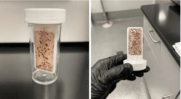
Figure 7.77. An aerobic dip slide.
Two-sided media increases the variety of microbes that can be identified, for example bacteria and fungi. A common incubation period for dip slides is two days at the manufacturer’s specified temperature. The planktonic population can then be estimated by comparing the mat of microorganisms that have grown on the agar nutrient to a reference chart.
Dip slides are easy to use and transport. However, varying agar types among manufacturers may not support all bacteria found in industrial water systems.
Petri Films
Petri films are flexible plastic plates that contain agar, nutrients and dyes to make microbes readily visible. Because of their thin size and ease of handling, Petri films are field or lab adaptable. Various Petri films are available for specific microbe identification, including aerobic bacteria, E. Coli, yeast, molds, and several others.
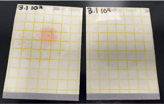
Figure 7.78. Petri films.
Adenosine Triphosphate Analyses
Adenosine Triphosphate (ATP) is the primary energy carrier for all living organisms. Because ATP plays a fundamental and important role in cellular energy production, metabolic regulation, and cellular signaling; numerous methods exist to measure this important compound. A common method utilizes an ATP-dependent enzyme, luciferase, to generate light. The light is captured by a detector known as a luminometer. The near-immediate reaction allows almost instant calculation of the microbiological concentration. The procedure involves mixing a water sample (some methods rely on concentrating the microbes in a sample using membrane filters) with a surfactant to lyse the cells, thereby releasing the ATP into solution. Luciferin and luciferase enzyme are then added with thorough mixing, followed by light measurement.
Below are brief descriptions of some of the most common laboratory microbiological tests.
Specific agar plates
Agar plates are circular Petri dishes containing a gelatinous, nutrient-enriched medium to support bacterial growth. The agar itself can be made in the lab from recipes and applied to the plates. Pre-poured agar plates are also available. Agar plates can be non-selective for general growth or can contain specific ingredients that promote the growth of a target organism like Pseudomonas or Enterobacteriaceae.
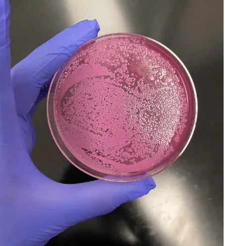
Figure 7.79. Microbe growth on an agar plate.
BART Tests
Biological Activity Reaction Tests (BARTs) are a simple field- or lab-based method of detecting specific bacteria in water samples. Samples are incubated over several days. Each BART has a unique visual indicator that allows the user to identify the presence or absence of specific bacteria. The target microbe population is estimated from the number of days of incubation until color or cloudiness appears in the tube.
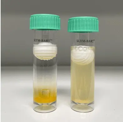
Figure 7.80. Nutrient vials, aka “bug bottles.”
BARTs are effective for identifying iron-related, sulfate-reducing, slime-forming, nitrifying, and denitrifying bacteria. The method is essentially a presence/absence type test, and does not provide population data. The tests can be handy in oilfield applications for general detection of anaerobic bacteria without the need for expensive equipment.
Flow Cytometry
Flow cytometry is a particle analysis technique that uses laser light to analyze physical and chemical characteristics of particles in a fluid stream. The size and quantity of suspended particles are measured by analyzing the eclipse-effect that the particles make as they pass in front of the laser. The amount of light scatter is associated with the complexity of the particles, which can be counted and sorted based on size and complexity. Benefits of flow cytometry include the specificity of the analysis, simultaneous analysis of a sample for multiple types of bacteria, and the ability to get results within hours as opposed to days. This technology is primarily employed in the medical industry.
Fluorescent Microscopy – Live/Dead Staining
Microscopy is a well-established method for visually analyzing bacteria. Fluorescent staining can differentiate various bacteria, and, with the use of dye combinations, can identify live and dead bacteria. Applying live/dead stain to a biofilm can help confirm if the chemical treatment program is effective in penetrating the biofilm and killing the bacteria within. While live/dead staining is an excellent visual technique and offers a rapid method of analyzing a sample, it does require a trained microbiologist, a controlled environment, and specialized instrumentation and reagents.
Sessile Microorganism Analyses
Most of the above-listed techniques are for speciation of planktonic organisms. If sessile colonies develop and are accessible during off-line inspections, the inspectors should collect samples for lab analyses. These can provide precise information on the organisms flourishing in that environment, which in turn offers guidance for modifications to the chemical treatment program.
Note: For personnel who may come in contact with sessile colonies or breathe the atmosphere around them during heat exchanger inspections or heat exchanger cleanings, the potential exists for exposure to legionella bacteria or other harmful microorganisms. Suitable personal protective equipment (PPE), including face masks, is a must.
Regular analysis of oxidizing biocide residual is extremely important to ensure consistent and proper dosages.
Prior to development of on-line monitoring methods, the standard procedure for either free or total halogen measurement was the DPD method. DPD is the acronym for N,N-diethyl-p-phenylenediamine. It reacts with oxidants in the water to form a colored complex, whose intensity is directly proportional to the amount of oxidant present.
DPD reacts with standard oxidants, including both free and combined residuals. Monochloramine is a prime example of the latter. Free or combined analyses require a different multiplication factor to convert the observed color to concentration. Another variable is reaction time. Free residual test results are typically available in less than 30 seconds, while the test for total residual usually needs 3–6 minutes for complete reaction. Each requires a separate test kit. While both include DPD and a pH buffer, the total-residual kit also includes potassium iodide and an additional buffer. These two compounds enhance color formation and enable less-reactive oxidants to combine with the DPD.
Mature, on-line oxidizing biocide measurement is available. A standard industry instrument is shown below.
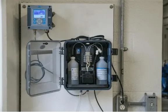
Figure 7.81. A Hach CL17sc analyzer. Photo courtesy of Hach.
The analyzer extracts a sample, and per the DPD discussion above, injects the dye and buffer. Following the proper reaction time, the instrument displays the oxidizer concentration, flushes the spent sample, and extracts a new sample. Thus, the analyzer can provide round-the-clock analyses, separated only by the time needed for reagent reaction. On-line monitoring can be of great benefit in promptly detecting biocide feed system malfunctions or water chemistry changes that increase biocide demand. Similar to grab-sample DPD analyses, either a free- or total-residual reagent is available for the analyzer.
Cooling water typically contains a number of oxidizing or reducing compounds. Oxidation-reduction potential (ORP) measurement is an analytical technique that provides data regarding the oxidizing or reducing power of the solution. When oxidizing biocides are utilized for microbiological control, their oxidizing potential usually dwarfs other species.
Common ORP probes typically have a working electrode containing platinum wire and a sealed silver/silver chloride counter electrode. These probes are rather robust and can often survive for several years under normal cooling water and process water operating conditions.
Some caveats exist with ORP for biocide residual monitoring. Measurements are not linear, especially at low concentrations. Temperature influences ORP; and temperature compensation, which requires an additional probe, is important for accurate readings.
Even with these caveats, ORP measurements can still provide meaningful information regarding biocide concentrations. With an oxidizing biocide present, the ORP will typically be elevated from baseline values to a range of 300–700 mV, depending on oxidizer species, concentration, temperature, pH, and presence of other species. ORP can verify that the oxidizer is present and will also detect if conditions move from aerobic (positive ORP) to anaerobic (negative ORP). Such changes may indicate serious contaminant influx.
The preceding sections outlined the prominent cooling water deposition and corrosion mechanisms, and control methods. The next sections outline deposition and corrosion monitoring techniques.
Cooling Water System Fundamentals introduced an indirect way to monitor heat exchangers by tracking inlet, outlet, and process fluid temperatures, and calculating heat transfer from these readings. Modern algorithms enable continuous data trending for quick detection of scale or microbial fouling.
Deposit coupons offer another option.

Figure 7.82. Deposit coupon
These coupons can be included with corrosion coupons in a bypass sampling system to collect suspended matter and mineral scales. Periodic extraction and visual examinations provide data on scale formation (or lack thereof). Weight density measurements and laboratory analyses of the deposit composition can provide valuable data.
Photographing the coupons immediately after extraction is important for documenting coupon conditions. One limitation of using coupons is that, since they are unheated, they do not match the surface temperature of heat exchanger tubes. As a result, deposition or corrosion observed on coupons may be less severe than what occurs in certain areas of the system. Two tools that more accurately simulate actual conditions are the deposition monitor and test heat exchanger.
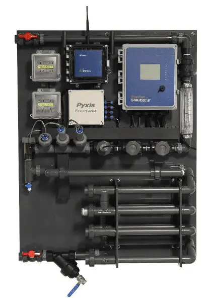
Figure 7.83. Deposition monitor
These units contain removable heat exchanger tubes. Return (hot) water from the cooling system is the feed, with a heated rod in the sample compartment. This configuration theoretically places the tube sample under the most stress of any heat exchanger in the entire cooling system. If scaling conditions are present, deposition should first occur in the test unit. Conversely, if the chemical treatment program prevents scale formation in the test unit, it can reasonably be assumed that the remainder of the system is clean. An obvious advantage is that if scaling occurs, the tube can be easily removed for deposit analysis. A key to successful application of this technology is a complete survey of the cooling system to assure that the conditions within the test unit are more severe than any of the process heat exchangers.
Corrosion Monitoring
The most fundamental corrosion monitoring method is by corrosion coupons. The coupons should be of the same metals that are in the cooling system. Coupons simulate corrosion rates similar to system components but may not fully reflect tube or plate surface conditions, especially with regard to temperature effects.
The most frequently-employed coupon for cooling water corrosion monitoring is C1010 (mild steel), but other common materials include stainless steel (usually one or more of the 300 series), admiralty brass, copper-nickel, aluminum, galvanized steel, and any other metallurgy that might be present.
New, cleaned, and pre-weighed corrosion coupons should be placed in service for a minimum of 30 days, with longer periods of 60, 90 and 120-days also recommended. This range provides short-term and long-term corrosion data.
The coupon appearance when first extracted shows the type and amount of surface fouling. This fouling may reveal various amounts of corrosion products, or perhaps other debris. Records and photographs upon removal are important, because deposition or corrosion materials may dislodge during shipment to the lab. Even odors, such as hydrogen sulfide, may be of value in identifying a fouling mechanism. Initial visual inspection often suggests a certain corrosion mechanism, but coupon cleaning in the lab and additional analyses may provide additional details regarding corrosion mechanisms. Ideally, of course, coupons will remain in nearly pristine condition, signifying the proper selection and performance of the chemical treatment programs.
The figure below outlines a fundamental corrosion report.
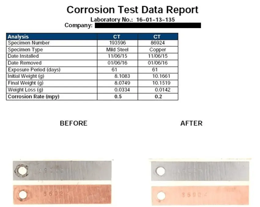
Figure 7.84. Typical corrosion test report and before and after coupon photographs.
The report and photos illustrate a mild steel and copper corrosion coupon subjected to the cooling water environment for just over two months. Only very slight general corrosion was detected, with low corrosion rates of 0.5 and 0.2 mpy, respectively. The coupon results suggest excellent corrosion control.
Corrosion Coupon Sampling Design
The following figure illustrates a common corrosion sampling arrangement, the “corrosion coupon by-pass rack” (coupon rack). The most common pipe material for cooling water sampling is CPVC, but steel pipe may be necessary for hot or pressurized water systems.
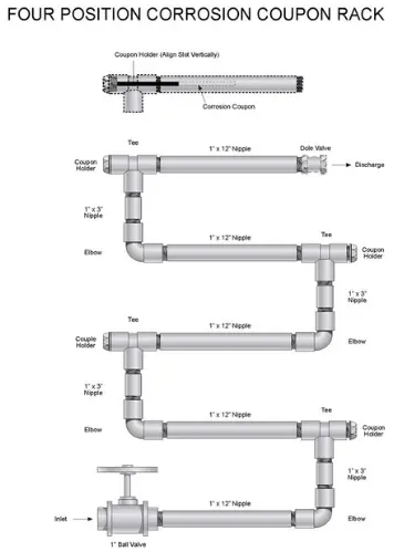
A prime feature of correct design is coupon orientation. As is evident above, the orientation is with the water flow along and not against the coupon. This configuration helps minimize eddy currents. The coupon holder typically has a “witness mark” on the hex head to assure proper orientation.
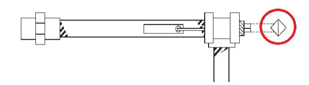
Figure 7.86. Illustration of the “witness mark.”
The coupon holder is electrically inert to prevent any galvanic effects. In hot systems with metal piping, the screw and bolt should be of the same metallurgy as the coupon, with connections separated by non-metallic washers.
The piping configuration in Figure 7.85 shows four potential coupon positions. This arrangement allows separate 30-, 60-, 90-, and 120-day sampling, or any other frequency desired, and with different metals. It is important that different metals be arranged according to the galvanic series from least to most noble. Also important with these systems is installation of valves that allow good sample flow control. Globe valves rather than gate valves are recommended.
A debate often arises over the use of pretreated versus untreated coupons. Either can produce beneficial data. If the concern is to determine how effectively the normal inhibitor concentrations in the bulk water can passivate the system, then untreated coupons are better. However, if the concern is about the potential for short-term corrosion like pitting, then pretreated coupons may be better so that initial flash corrosion does not mask other issues.
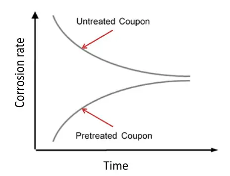
Figure 7.87. Relative corrosion rates for treated and untreated coupons over time.
The untreated coupon will experience an initial rapid flash corrosion, after which the rate decreases as the coupon becomes passivated. The pretreated coupon has low initial corrosion rates until the inhibitor protective film reaches equilibrium with the bulk system at which point the coupon will mimic the conditions in the water system. Over an extended time period (60 to 90 days) the corrosion rates approach each other.
Online Corrosion Rate Meters
Corrosion meters are available to measure corrosion electronically. The advantages are instant and continuous measurements. However, they are significantly more expensive than corrosion coupons.
Two primary types of corrosion meters are common: Linear Polarization Resistance (LPR) and Electrical Resistance (ER). This section focuses on LPR, which measures the actual milli-voltage readings produced during corrosion.
Linear Polarization Resistance
The instrument can be equipped with electrodes of the metal of interest, which then corrode by the normal mechanisms.
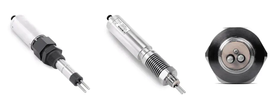
Figure 7.88. Examples of online LPR corrosion rate sensors (left) and electrodes (right). Courtesy of Pyxis Lab, Inc.
The technology is applicable for cooling water and other water systems, including:
As the figures indicate, both 2- and 3-electrode probes are common. LPR meters can instantaneously measure corrosion rates from 0.01 to 200 mils per year (MPY) and pitting from 1.1 to 100 pitting units using a proportionality factor that relates the electrical polarization characteristics of the probe to its corrosion rate.
Corrosion Testing in the Laboratory
Electrochemical techniques, e.g., cyclic polarization, are common in the laboratory to evaluate material susceptibility to localized corrosion. Critical parameters such as corrosion potential, pitting potential, corrosion current, and re-passivation potentials can be determined from the cyclic polarization experiment.
The schematic of the electrochemical setup and the representative cyclic polarization graphs are shown below.
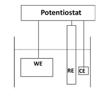
Figure 7.89a. Schematic of the electrode arrangement. WE = Working Electrode; RE = Reference Electrode; CE = Counter Electrode
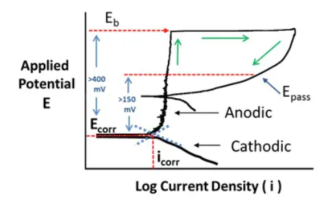
Figure 7.89b. Schematic of the cyclic polarization curve. Ecorr = Corrosion Potential; Eb = Breakdown Potential; Epass = Re-passivation Potential; Icorr = Corrosion Current.
From the cyclic polarization graphs, important parameters can be calculated such as:
Pitting potential (Epit) = Eb – Ecorr | Eq. 7-32
Re-passivation Potential (ERP) = Epass – Ecorr | Eq. 7-33
Generally accepted is that an Epit value of greater than 350–400 mV coupled with an ERP of greater than 150 mV means there is minimal possibility of localized corrosion, and that the alloy is suitable for long-term use in that environment.
Figure 7.92 illustrates the cyclic polarization curves for a 304-stainless steel specimen in Richmond, Virginia tap water at a temperature of 150°F and with the chloride concentration boosted to 750 ppm. Various critical corrosion parameters can be derived from this graph and are shown in Table 7-4. The data outlines the corrosion protection provided by ChemTreat’s RPSI chemistry.
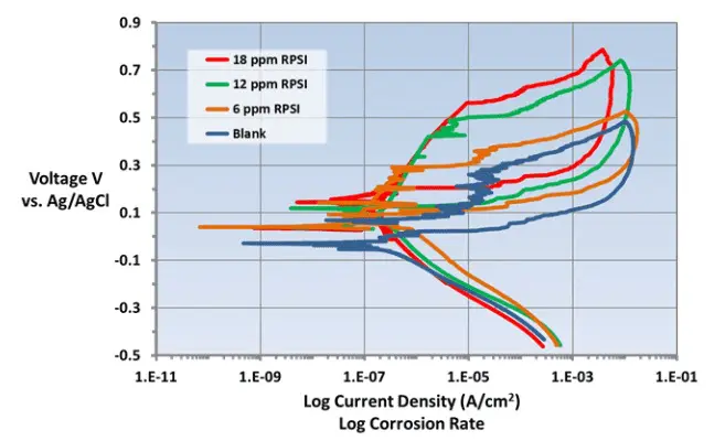
Figure 7.90. Cyclic voltammetry graphs of Type 304SS in Richmond tap water with 750 ppm chlorides at 150°F
Table 7-4.
Various corrosion parameters calculated from the cyclic polarizations curves shown in Figure 7.92.
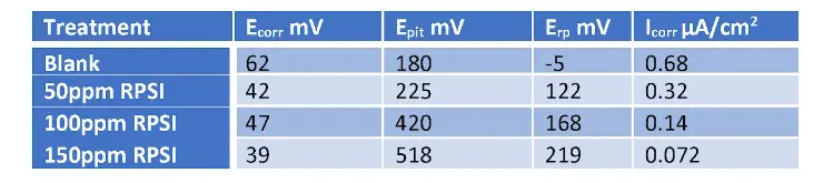
It is clear from this data that the pitting and re-passivation potentials increase with increasing RPSI dosage. 100 ppm RPSI satisfies the requirement of Epit greater than 400 mV and ERP greater than 150 mV and confirms that Type 304 SS does not undergo localized corrosion under these conditions.
It has been observed that certain steels, notably 304 and 316 stainless steel, are susceptible to stress corrosion cracking (SCC) when exposed to low chloride concentrations combined with elevated temperatures. The ability of RPSI to potentially protect 304 SS from SCC has been demonstrated in laboratory tests, in which U-bend stressed specimens were placed for 15 days in a bath of 105o C tap water spiked with 1,000 mg/L of chloride. The figures below show the condition of the samples following the test.
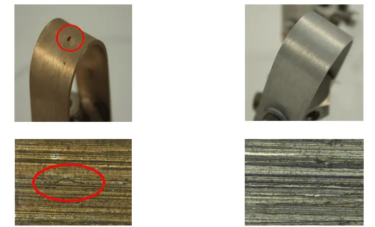
Figures 7.91. Untreated 304 SS coupon (left) and treated coupon (right).
The untreated specimen is clearly tarnished and pitted. The specimen exposed to the same solution containing the RPSI corrosion inhibitor shows no evidence of tarnish or pitting. Under magnification, cracking is clearly evident at the bend of the untreated specimen while the treated specimen shows no cracking.
This section presents general passivation guidelines for cooling systems. Too often, design engineers and plant personnel view pre-operational cleanings and system passivation as minor or unnecessary items. In these cases, the procedure at most might consist of filling the system with water, hydrostatic testing (where applicable), and then unit startup. Frequently, the water treatment provider is brought into the discussion much too late to offer information and advice on the criticality of proper pre-cleaning and passivation. This discussion outlines general recommendations for common applications, with the understanding that every cooling system has individual characteristics and metallurgies. Consultation with reputable chemical treatment experts is necessary to develop precise cleaning and passivation procedures.
New cooling systems often contain debris left behind from the construction and installation phases, along with oil and grease residues and corrosion products from flash rusting. It is paramount to have a cleaning and passivation plan in place and performed prior to actual system commissioning. The following discussion is divided into three categories.
A much more detailed outline of cleaning, passivation, and layup procedures is available in ChemTreat’s Technical Bulletin 82.28
Pre-Operational Cleanout and Passivation-General Guidelines
Along with silt, dirt, oils, and rust, new cooling towers may also accumulate organic slime and algae in sumps and decks that have been flooded for fire protection. These organisms can foul and plug condenser and heat exchanger tubes, cooling tower fill, and other equipment.
General Guidelines for All Cleanings/Passivation
Prior to start of the cleaning and passivation procedure:
Note: Arrangements for drain to sewer, holding ponds, or other disposal of cleanup wastes must be in place prior to cleaning. While this wastewater is not typically hazardous, it usually contains unacceptable levels of suspended solids and oils. Also, the pH of the discharge may exceed plant NPDES or POTW (publicly owned treatment works) limits. Severe penalties may be assessed if unauthorized and improper wastewater discharge occurs. Frequently, the spent cleaning solution can be sent to a POTW if prior arrangements have been made.
Cleanup and passivation steps can be performed together or in immediate succession. In most cases, the tower water system is first cleaned and flushed and then passivated with strong inhibitor concentrations prior to placing the system into operation. The following steps are common:
In general, the chemicals employed for initial cleaning and passivation include agents to maintain a neutral or mildly alkaline pH, surfactants for oil and grease removal, and an anti-foaming agent. A pyrophosphate to maintain a pH of 10 may be beneficial for enhanced passivation.
After the chemicals have been added, the tower water should be circulated at normal operating rates for four to eight hours to ensure proper distribution and cleaning. Correctly-applied procedures will produce passivated steel.
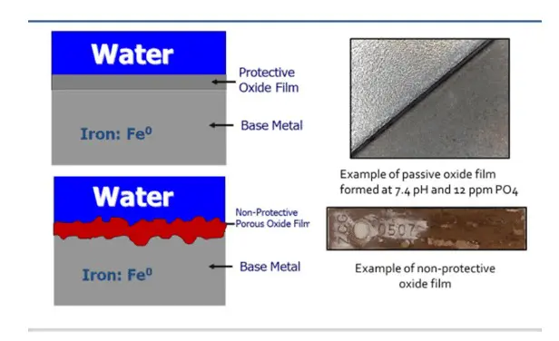
Figure 7.92. Comparison of correct vs. incorrect passivation.
At process conclusion, the tower, cooling system piping, and heat exchangers should be drained and flushed as thoroughly as possible to remove oils, silts, and biological sludge from the system. Again, arrangements should already be in place to dispose of this wastewater.
If the cooling system will remain filled but on standby for more than three days, protection with a non-oxidizing biocide is recommended. A copper-free isothiazolin product is common. At a minimum, the tower water should be circulated for one to two hours weekly prior to startup, but 1–2 hours daily is ideal.
For systems containing galvanized components, special procedures are necessary to ensure that the galvanized materials develop a proper passivation layer. The table below outlines recommendations from three cooling tower manufacturers.
Table 7-5:
Galvanized Cooling Tower Original Equipment Manufacturers’ Water Chemistry Recommended Values and Ranges. Source: “White Rust Prevention – An Industry Update and Guide Paper – 2012”, Association of Water Technologies (AWT).
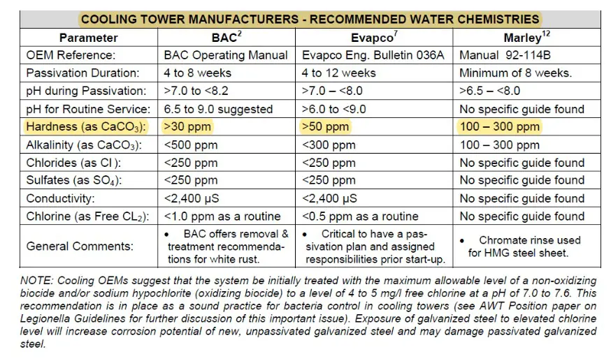
Note that some variability exists in the recommended chemistry guidelines, but each program is designed to produce a tight hydrated zinc carbonate compound on the metal surface. The chemical formula of this compound is thought to be 3Zn(OH)2∙ZnCO3∙H2O.
If this conditioning is omitted, or if subsequent operation raises cooling water to an elevated pH, zinc will react with the water to form a porous, gelatinous zinc hydroxide, which then reacts with carbonate and converts the material into a white, waxy deposit known as “white rust.”
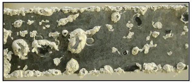
Figure 7.93. Photo of white rust.
If white rust develops on galvanized metal, the deposits become increasingly porous with an increasing loss of metal underneath. This corrosion will eventually expose the underlying carbon steel to attack.
Once the passive coating has been properly established, several of the cooling tower manufacturers recommend a normal pH operating range of 6.5–9.0. This is well within the guidelines for the common deposit- and corrosion-control guidelines discussed above. Resources for further information include the Cooling Technology Institute and specific cooling tower manufacturers.
Following an extended shutdown or new installation, flash rusting, and stagnant conditions can take a dramatic toll on the condition of chiller networks. Failure to properly clean and passivate a system prior to startup may result in repeated unplanned failures. If the opportunity exists to take photos of key equipment conditions before and after cleaning, the pictures will allow evaluation of cleaning efficacy. Complete knowledge of system metallurgy is a must for selection of the proper cleaning and passivating chemicals. Carbon steel typically constitutes the primary system metallurgy, but copper alloys and stainless steel may also be present. If aluminum components are in the system, special precautions are needed to protect this metal.
General Pre-Cleaning Procedure
The cleaning/passivation process is different for every application and may be very specific for certain facilities such as data processing centers.
At many facilities, equipment operates 24/7 with little downtime. However, for those times when systems must be taken off line, well-designed and conducted layup procedures are necessary to prevent serious corrosion. The combination of cold water and oxygen can be very destructive to some alloys, most notably carbon steel. Also, microorganisms can settle and proliferate in stagnant water. Subsequent tube or pipe failures from MIC have been well documented.
If possible, draining and drying equipment is often the best method to minimize corrosion. Dehumidified air circulation (DHA) can be very effective for drying. An example of this process is outlined in Fundamentals of Industrial Boilers and Steam Generating Systems for protection of steam turbines during outages. Often, however, water must remain standing in systems so that they can be started on short notice. In these cases, several steps are recommended for metal protection. These include:
Cooling water chemistry, and minimization of corrosion, scaling, and microbiological fouling, is a complex subject. Many factors influence these phenomena. It is ChemTreat’s hope that this chapter will provide useful information for plant owners, operators, and technical personnel in developing effective cooling water treatment programs.
ChemTreat is committed to providing expert water treatment solutions. Our innovative and customized water treatment solutions help control corrosion, scale and biofouling in cooling systems across a variety of industries. Contact ChemTreat to get in touch with your local representative to learn how ChemTreat can help your business today.

Senior Technical Staff Consultant
Pete Elliott is a trusted technical expert with over 30 years of experience in water treatment solutions for utility and thermal processing systems. In his line of work, Pete focuses on producing best practices for efficient plant operations, energy and water conservation, and asset protection and preservation. He has published technical papers for the Cooling Technologies Institute (CTI) and the Association of Water Technologies (AWT). Pete holds a B.S. in Civil Engineering from Villanova University, and served as an engineering officer in the United States Navy.

Director of Cooling Water
Rajendra P. Kalakodimi is the Director of Cooling Water at ChemTreat. He received an MS degree in physical chemistry at Andhra University and a PhD in electrochemistry at the Indian Institute of Science in Bangalore in 2003. While in India, Dr. Kalakodimi served as the Engineering Technical Leader at the GE India Technology Centre in Bangalore and as Product Manager for Chemicals and Monitoring Solutions for GE Water. He has more than 20 patent filings, 20 international publications and various conference presentations.

Technical Service Consultant
Richard H. Tribble is a graduate of Virginia Commonwealth University and has been in water treatment for 26 years. He has developed a multitude of high performance cooling product formulations, has 6 patents under his name and has authored numerous papers. He currently works as the Closed Loop Product Champion for ChemTreat as well as specializes in root cause failure analysis.
The ChemTreat Water Essentials Handbook would not have been possible without the contributions of many people. See the full list of contributors.