-
USA - English
- Locations
- SDS Access
- CTVista®+ Login

By Katie Perryman, Ed Sylvester, and Brad Buecker, ChemTreat, Inc.
This article originally appeared in The Analyst, an AWT publication.
High-purity water is typically a must for power-producing steam generators, as the high-temperature/pressure conditions require control of impurities to low part-per-billion (ppb) concentrations to prevent serious corrosion and fouling. For the thousands upon thousands of low-pressure boilers at industrial plants around the country, however, water-purity requirements are usually not as stringent. Yet, incidents where poor design or failures in the makeup water treatment system have induced severe scaling and corrosion have been recorded for decades and continue to occur. These can lead to lost production and costly equipment repair or replacement. This article provides insight into the importance of makeup water treatment for low-pressure boilers and outlines modern technologies for producing good-quality makeup water at reasonable cost.
Low-pressure steam (pressures below 900 pounds per square inch gauge [psig] in general, and often between 50 and 600 psig) is used at many industrial plants around the country. For example, steam typically serves numerous processes at refineries, including as an integral heat source in atmospheric distillation, and in cracking and reforming processes. Steam feeds turbines for blast furnace air production at integrated steel mills; digesters and concentrators at paper mills; evaporators, crystallizers, and reaction vessels at chemical plants; and building heat systems everywhere. The list goes on and on.
The stimulus for this article comes from direct experience by the authors and too-frequent reports from our colleagues, who, upon entering plants for the first time find steam generators with serious scaling, corrosion, or steam purity issues that can be directly traced back to either poor design or inadequate attention to the makeup water system (and often condensate return chemistry). This frequently seems to occur as the result of plant management, operators, or technical staff focusing on process chemistry and engineering, with steam generation (and cooling water systems) appearing as rather nebulous entities that require less attention.
Most of the boilers in large industrial plants are the watertube style, frequently of the package type, although large boilers may be field-erected. Steaming rates (pounds per hour [lb/h]) are usually in the five to six-figure range. Commonly, these boilers include superheaters to raise the steam temperature above the saturation point and ensure the steam has the proper energy and/or remains dry until the point of use. For boilers that supply turbines, superheating is required to prevent excessive condensation in the turbine that could damage blades.
Probably from the time humans first began to heat water for personal needs, our species has observed deposition in heated vessels. These issues became much more acute following the invention and expanded use of the steam engine during the Industrial Revolution of the 18th and 19th centuries. The primary culprit was (and still often is) calcium carbonate deposition.

This equation outlines the reaction of calcium ions (Ca2+) and bicarbonate alkalinity (HCO3-) that can occur in hot water systems and boilers. A critical point to note is that CaCO3 is an inversely soluble salt, whose deposition potential increases with increasing temperature. As Figure 1 clearly illustrates, it is not a mechanism that has been relegated to the past.
As steam generators increased in pressure and power in the last century, methods to minimize and control CaCO3 scaling became necessary. A common solution from the 1930s onward has been makeup water sodium zeolite softening, a technology that became practical with the development of synthetic ion exchange resins (Figure 2).
Each of these beads contains billions of active sites, which, for sodium softening, are typically sulfonic acid groups with sodium attached (SO3–Na+). Figure 3 illustrates a basic configuration of a softening vessel.
As makeup water passes through the vessel, calcium (Ca2+) and magnesium (Mg2+) exchange for sodium. The strongest affinity is for calcium followed by magnesium, so as a service run progresses, the resin develops stratified layers.
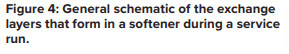
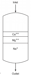
The softened stream, with hardness removed, still contains the other dissolved ions, including alkalinity, chloride (Cl-), sulfate (SO42-), and silica (SiO2). When the bed reaches exhaustion, it is regenerated with a brine solution that drives the hardness ions off into a waste stream, which is discarded.
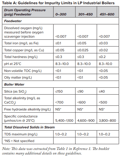
At this point, several features of sodium softening require some extra discussion. Many low-pressure steam-generating systems have been designed with sodium softening as the core boiler makeup treatment method, with no further treatment. And indeed, this may be sufficient for numerous steam generators. Table A outlines some general guidelines, extracted from a well-known American Society of Mechanical Engineers (ASME) source, regarding impurity limits in low- to medium-pressure watertube industrial boilers.
The data indicates that a significant amount of alkalinity can be tolerated in low-pressure boilers, and for many applications, some alkalinity may be desirable, as it helps protect metal surfaces from corrosion, a point we will return to later. However, HCO3, upon reaching the boiler, is in large measure converted to CO2 via the following reactions in Equations 2 through 4.
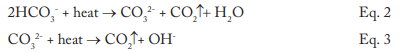
The conversion to carbon dioxide (CO2) from the combined reactions may reach 90%. CO2 flashes off with the steam, and when the CO2 re-dissolves in the condensate, it can increase the acidity of the condensate return.

Although the pH generated by this reaction has a relatively mild lower limit, the acidity is more than enough to cause significant carbon steel corrosion in condensate return systems. For example, 3 parts per million (ppm) of CO2 in pure steam condensate will lower the pH to 5.26. If dissolved oxygen is present in the system, corrosion can be greatly magnified.
A unit operation that can minimize production of CO2 in the steam generator is illustrated in the following fundamental diagram.
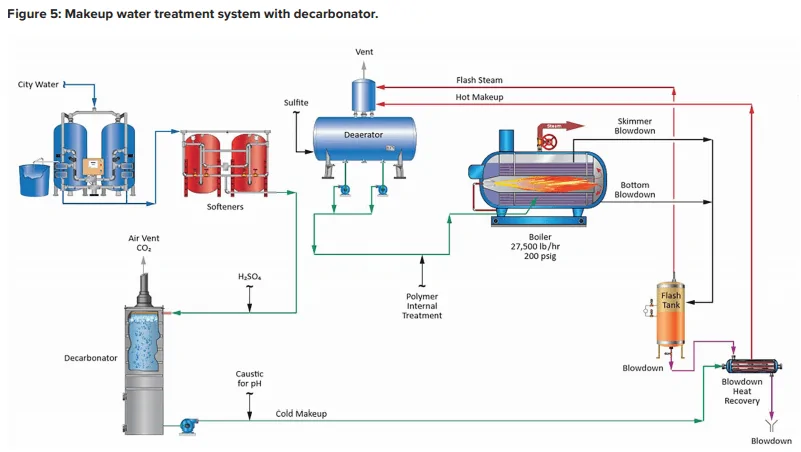
Note the inclusion of a forced-draft decarbonator with acid injection to the feed. The acid conditioning forces Equation 4 to the left, and a well-designed decarbonator can reduce the CO2 concentration to a low parts-per-million (ppm) level. Caustic feed downstream of the decarbonator then raises the pH of the water to make it less corrosive on its path to the boiler. Note: If steam attemperation is provided by direct injection of feedwater from the deaerator, then caustic cannot be used to raise the pH. A nonvolatile compound (e.g., ammonia, an amine) is required.
Another issue briefly hinted at above now requires a bit of discussion. With too-frequent regularity, when technical representatives begin visiting a plant for the first time, they find boilers with scale deposition, corrosion, or both. In many cases, plant personnel will reveal softener problems that have led to hardness breakthroughs. Equation 1 and Figure 2 illustrate the potential effects of such difficulties. But even a softener/decarbonator operating properly still allows many ions, such as chloride and sulfate, to enter the boiler. Without close attention to boiler water chemistry and boiler blowdown control, the accumulation of these ions can cause corrosion and other problems, including foam formation in boiler drums. This in turn can lead to steam contamination and downstream issues. To re-emphasize, steam generator makeup system and boiler water chemistry control require just as much attention as process operations.
For modern makeup systems, reverse osmosis (RO) offers a reliable alternative to softening, where even basic systems can remove 99 plus percent of all ions from water. The osmosis process has been known for years. Two solutions of different concentrations, when separated by a semi-permeable membrane that only allows water to pass, will induce water in the dilute solution to move through the membrane to the other solution to balance the concentration. This phenomenon induces an osmotic pressure on the membrane until the solutions reach equilibrium. As the name reverse osmosis implies, the reaction is operated in reverse, and pressure produces purified water from a more concentrated stream.
The potential application of RO as a makeup water treatment method became well known in the last century and became popular with the development of and improvements to spiral-wound membrane technology.
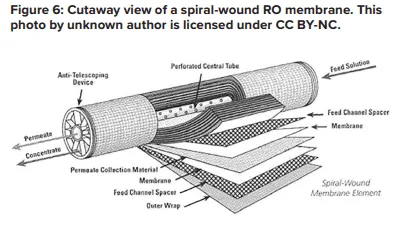
A flat membrane sheet has several layers as a backbone, which are all wrapped around a central, perforated plastic core. Feed enters the front end of each element and flows along the feedwater carrier while pressure pushes water through the membrane. The purified water, known as permeate, flows to the central core, and the increasingly concentrated feedwater (reject) exits the element.
Each RO pressure vessel typically has several elements arranged in a series.
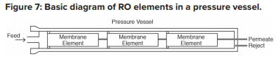
O-rings seal each element along the walls of the pressure vessel so that the feedwater does not short-circuit any of the elements. A typical RO pressure vessel will have five or six elements.
The configuration is designed to process the water via the mechanism known as crossflow filtration.
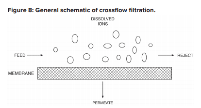
The feed flows parallel to the RO membranes, and pressure forces pure water through the membranes while the impurities are carried away with the reject. Only a few of the smaller monovalent ions (Na+, Cl-, silica, HCO3) pass through the membrane. However, while crossflow filtration is designed to keep impurities suspended in the reject stream, it is inevitable that even with exceptionally clean makeup, compounds will gradually build up on the membrane surfaces. Typically, residual suspended solids that are not captured by pretreatment will accumulate in the lead membranes of an RO system. Conversely, because dissolved ions concentrate as the water passes from one membrane to the next, scaling becomes an increasing concern in downstream elements.
The basic RO system is a two-stage, single-pass type, as outlined in Figure 9.
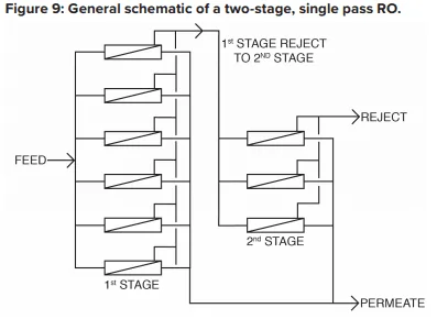
A critical feature of RO is illustrated in this diagram. With “normal” feedwaters, approximately 50% of the feedwater is converted to permeate in each first-stage pressure vessel. This means that without further processing, 50% of the feedwater would be wasted. In the two-stage design shown above, the raw feedwater flows through six parallel pressure vessels in the first stage, and the reject from these vessels is routed through three additional pressure vessels in the second stage. Total water recovery increases to 75%.
For some applications, especially those for ultra high-purity water production, two-pass RO is common. In this configuration, the permeate from the first pass is treated in a separate set of membranes. Because the feedwater has already been significantly purified, 85% to 90% recovery from the second pass is achievable. The reject is recycled back to first pass inlet, and no water is discharged to waste from the second pass.
RO has become quite popular for several applications in recent years, especially for steam-based power generating units. RO plus polishing mixed-bed ion exchangers or electrodeionization can produce the high-purity water needed for steam generation
RO membranes, especially the lead elements, are susceptible to particulate fouling. An important measurement for determining this fouling potential is the silt density index (SDI). Usually, 5-micron (µm) depth filters are placed ahead of the RO to minimize the potential for particulate fouling. The SDI tests should be performed on the effluent from these filters. The SDI test is straightforward. A flowing sample of RO feedwater, downstream of the cartridge filters, is routed through a 0.45-µm filter at 30 psig pressure. Measurement is taken of the time for 500 milliliters (mL) of water to pass through the filter at the beginning of the test (ti) and again after 15 minutes (tf). The SDI is calculated as shown in Equation 5:
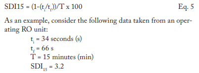
A general rule of thumb is that the SDI should be at least below 5 and preferably below 3. However, SDI should not be the only criteria that determines suitability of a RO application. The type of water and/or the nature of contaminants should also be considered. For example, in one application, the SDI readings of the RO feed always ranged between 1 and 3. Yet the membranes fouled with exceptionally fine iron oxide particles.
Scale formation is another issue that requires attention. When water flows through an RO pressure vessel, the concentrate continually accumulates dissolved solids, which increases the scaling potential. Calcium carbonate and sulfate can build up to a point where precipitation begins to occur. Other possible deposits include silica and alkaline metal silicates, strontium sulfate, barium sulfate, and calcium fluoride. While pretreatment can reduce the concentrations of many scale-forming compounds, the remainder may still cause problems. Barium and strontium sulfate scales are especially difficult to remove. Reputable membrane manufacturers have developed programs to calculate the solubility limits for these salts. The program will warn the user if any solubility limit is exceeded. The programs also provide “normalization” calculations of the RO system, as is described later.
Antiscalant feed is typical for RO systems. Common antiscalants include polyacrylates and phosphonates. The correct antiscalant or blend can control calcium sulfate at a factor of 7 above the saturation limit, strontium sulfate 800% above the saturation limit, and barium sulfate 6,000% above the saturation limit.
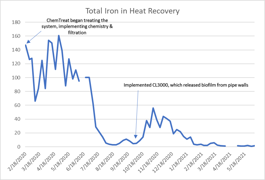
Pretreatment chemicals can affect membrane performance. Coagulating agents of the cationic variety and, most notably, aluminum compounds and some organic coagulants/flocculants, are particularly troublesome to RO membranes. If these agents are present, methods to remove them should be considered. Chlorine, usually introduced as bleach, injected into the primary plant makeup to control microbiological fouling will react with nitrogen atoms in RO membranes and irreversibly damage the materials. Chlorine should be removed upstream of the RO, but the absence of any biocides leaves the membranes in danger of microbial attack. Figure 10 shows how biofouling can damage a membrane element.
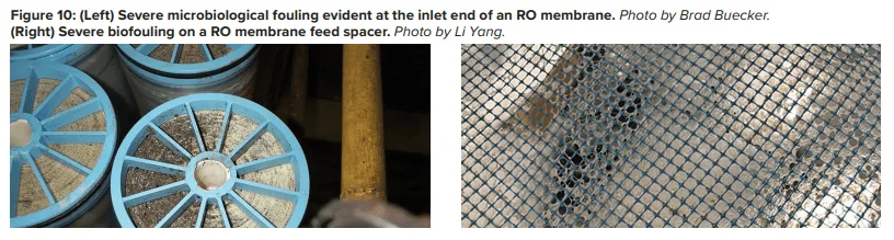
Biological fouling can cause irreversible damage to membranes because the deposits cannot be completely removed by standard cleaning methods. It is imperative to minimize conditions that can lead to microbiological deposition. Alternative techniques to chlorine are available to minimize microbe deposition within membranes. One is periodic treatment with a non- or mildly oxidizing biocide (frequency depends on fouling potential). A popular choice is dibromo-nitrilo-propionamide (DBNPA). A DBNPA chemical diagram is shown in Figure 11.
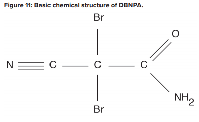
DBNPA is a fast-acting biocide that can be readily removed from any discharge by raising the pH to around 9, or commonly, treating with sodium bisulfite. Another possibility is a specialized version of chlorine dioxide (ClO2).A Such a product may sound surprising, as chlorine dioxide can act as a strong oxidizer in cooling water applications. However, in this case, the chlorine is not free, and thus does not react with nitrogen atoms in the membranes.
Even with well-controlled pretreatment and antiscalant chemistry, RO membranes will still collect deposits. The lead elements gather residual colloidal and suspended solids, while the downstream elements, especially those in the second stage, see higher concentrations of dissolved ions that may precipitate. Compounding the issue is that the pressure required to push water through the membranes can hold some of these particles in place. If impurities accumulate unchecked, the eventual result is irreversible membrane fouling.
Therefore, normalization programs are key for determining the need for and scheduling of RO cleanings. Temperature has a significant impact on permeate flux and pressure, and temperature changes can mask flow and pressure variations caused by suspended solids or scale buildup. Normalization programs use temperature, pressure, and flow measurements to provide corrected values for all temperature conditions. A common rule of thumb is to schedule a cleaning when the normalized value has dropped 10% to 15% from the baseline. Normalization programs can also help detect an increase in salt passage caused by a failed or degraded membrane, which might otherwise be attributed to temperature effects.
A two-step cleaning process is often employed to remove the potentially wide variety of foulants that can accumulate in RO membranes. Typically, in the first step, a high-pH (12 at 95°F) solution is circulated throughout the membranes. The alkaline solution removes organic compounds, microbiological and otherwise, that have accumulated. This stage is followed by a rinse and often a low-pH stage with citric acid as the key ingredient. Low pH helps remove soluble mineral salts such as calcium carbonate, while the citric acid will chelate metals, most notably iron. The inclusion of a heater in the cleaning loop can significantly speed up the process.
An important concept is to clean each stage separately. Otherwise, extracted impurities from one stage may foul the other, and vice versa. Also, cleaning systems are typically designed with cartridge filters in the cleaning loop to collect solids during the process. These filters should be replaced after each step in the cleaning.
The foregoing is general guidance only. Please consult your RO manufacturer for specific guidance.
As noted, a typical two-stage, single-pass RO system recovers approximately 75% of the inlet feed and produces a waste stream (reject) of the remaining 25%. This stream must be disposed somewhere. For plants with cooling towers, the basin of one of the towers is often an ideal location for the reject. Alternately, many plants have wastewater treatment facilities to condition discharge water before release to the environment. RO reject is basically plant makeup concentrated by a factor of four, so it should not overload the wastewater treatment equipment.
A variety of treatment programs are available for low-pressure boilers, which may include phosphates, organic polymers, and sometimes chelating agents. These should be tailored to the chemistry of the water entering the boiler from both the makeup source and condensate return. A change from softened water to RO permeate can have a significant impact on boiler water treatment and even feedwater treatment. Higher purity waters are often known as “hungry” water because the lack of dissolved ions induces metals to give up ions to the water. Bicarbonate ions, even though they can react with calcium to form scale, will in many cases form a loose, protective layer on metals. For plant personnel considering a change from softened water to RO, these and other factors should be considered before making the switch. And, given that boilers should see a lower influx of hardness, the treatment program may need modification to account for this changed chemistry. A factor of major importance at many plants is the ratio of makeup water to condensate return. If the latter is much higher than the makeup flowrate, condensate return chemistry can dominate the selection of the best boiler water treatment program.
ChemTreat's CL3000, a specialized version of chlorine dioxide (CIO2), is the cleaning product referenced in the text.
Disclaimer: This discussion represents good engineering practice developed over many years. However, it is the responsibility of plant owners, operators, and technical personnel to set up reliable chemical feed, control, and monitoring systems based on consultation with industry experts. Many additional details go into the design and subsequent operation of these technologies than can be outlined in this article.
 Katie Perryman is manager of ChemTreat’s pretreatment team as well as the company’s Early Career Program. Her career at ChemTreat has focused on membrane separation and ion exchange with an emphasis on consulting and troubleshooting of pretreatment systems in different water treatment applications. Ms. Perryman holds a B.S. Chemistry.
 Ed Sylvester Editor of filtration, ion exchange, and membrane technologies at ChemTreat. He has more than 41 years of experience in water treatment, including product development, troubleshooting, corporate training, and conference presentations. Mr. Sylvester may be contacted at edwards@chemtreat.com.
 Brad Buecker (B.S., Chemistry, Iowa State University, Ames, IA, USA) is a senior technical publicist with ChemTreat. He has many years of experience in or affiliated with the power industry, much of it in steam generation chemistry, water treatment, air quality control, and results engineering positions with City Water, Light & Power (Springfield, IL, USA) and the Kansas City Power & Light Company’s (now Evergy) La Cygne, KS, USA, generating station. He also spent two years at a chemical manufacturing plant and an additional 11 years at two engineering firms. He is a member of the ACS, AIChE, ASME, AIST, AMPP (NACE), the Electric Utility Chemistry Workshop planning committee, and the Power-Gen International planning committee. Mr. Buecker has authored many articles and three books on power plant topics.