-
USA - English
- Locations
- SDS Access
- CTVista®+ Login

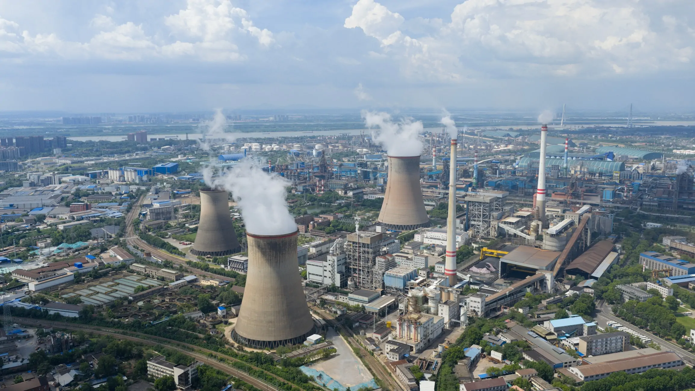
Coal-fired power generation for industrial steam production faces unique challenges in navigating regulatory oversight regarding environmental impact. Combustion of coal generates atmospheric pollutants, such as fine particulate matter, sulfur dioxide (SO₂), and nitrogen oxides (NOₓ), which are expensive to remove from flue gas emissions. Further, coal combustion emits more carbon dioxide than any other fuel source. It also generates substantial quantities of bottom ash and fly ash, which are often mixed with water and subsequently deposited in one or more retention ponds spread throughout the country. Leachate from ash ponds, which contains heavy metals and metalloids, has led to the contamination of surface and underground water supplies. Consequently, efforts are underway at many sites to drain and decommission ash ponds.
Many coal-fired power plants remain in operation, particularly in Asia. Advocates of carbon capture and sequestration (CCS) maintain that coal remains a viable boiler fuel, primarily due to the capability of CCS to remove and store CO₂ underground, minimizing carbon dioxide release. Accordingly, this chapter examines key aspects of boiler fireside chemistry and the processes that release impurities during coal combustion. Additionally, this chapter explores potential control methods to minimize pollutant discharge from coal’s primary fossil replacement, natural gas.
Coal is compressed plant matter that is transformed into a high-carbon material over millions of years. Age, vegetation type, and the location of the deposit formation are all significant factors in the quality of a coal deposit.4
Vegetation that dies on solid ground decomposes through atmospheric processes into carbon dioxide and water. When vegetation dies in a swamp, however, a much different process occurs. First, microorganisms consume hydrogen and oxygen, which increases the carbon content. This mechanism, known as the biochemical phase of coalification, is self-limiting, as the bacterial action generates organic compounds that eventually become lethal to the organisms themselves. Over time, the partially decomposed matter becomes overlaid by other material, including more vegetation and soil. This process produces two principal effects: It places the material under increasing pressure and moves the deposits deeper underground where temperatures are warmer.4
The combination of pressure and heat causes additional oxygen and hydrogen loss in the geochemical phase of coalification. The results are illustrated in Table 1, which shows the primary chemical composition of wood up to the most mature coal, anthracite.4
Table 5-1 – General Carbon, Hydrogen, and Oxygen Concentrations of Various Coals and Precursors (Source: Reference 2)
|
Composition by % weight (Dry and Ash Free Basis) |
|||
|
Material |
Carbon |
Hydrogen |
Oxygen |
|
Wood |
49 |
7 |
44 |
|
Peat |
60 |
6 |
34 |
|
Lignite |
70 |
5 |
25 |
|
Subbituminous |
75 |
5 |
20 |
|
Bituminous |
85 |
5 |
10 |
|
Anthracite |
94 |
3 |
3 |
Generally, carbon content increases as coal matures.
The complex carbohydrates within vegetation are constructed from the sugars and starches produced by the plant through photosynthesis.5 During the coalification process, some compounds metamorphose to low weight organic molecules unbound to the main coal structure. The smaller organic compounds, known as volatiles, vaporize as temperatures increase. Volatile compounds are progressively expelled during coalification, resulting in coals of higher maturity exhibiting a reduced volatile matter content.6
Age is not always the primary factor in the maturity of coal, as pressure and temperature are often more important. Coals buried deep and located in high-temperature locations, such as a region of volcanic activity, mature at a faster rate than older coals subjected to less heat and pressure.
Table 5-2 – Coal Classification by Rank. Courtesy of The Babcock & Wilcox Company.
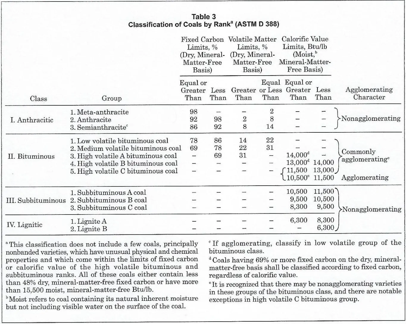
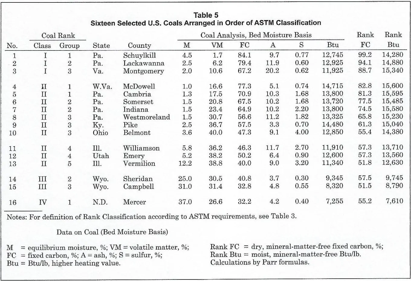
Table 5-3 shows the main properties of some selected coals from around the U.S.
Table 5-3 – Properties of 16 U.S. Coals. Courtesy of The Babcock & Wilcox Company.
This table outlines some notable features of the distinct forms of coal. Examples include:
Though worldwide coal-fired power generation is declining, the residual effects of the technology remain. The greatest concern is mitigating the impacts of potentially toxic materials stored in ash ponds and wet flue gas desulfurization (WFGD) wastewaters. Where do these coal impurities originate?
While certain impurities accumulate during the plant growth phase, many originate from external sources, which are heavily influenced by the geographical location and environmental conditions during coal formation. Fuel-bound nitrogen is the main contributor to the formation of nitrogen oxides (NOx) during combustion. As air (which contains 78% elemental nitrogen (N2)), is used for combustion, NOx is formed through the reaction of N2 and O2 in the furnace. However, this process typically produces less NOx compared to that originating from fuel-bound nitrogen.
Peat exhibits a high moisture content. However, even in mature coals, such as bituminous, many cracks and crevices allow the passage of water, the primary source of impurities. Iron sulfide (FeS2), a commonly found impurity, is believed to have originated from swamps flooded with brackish water containing sulfates. Anaerobic bacterial decomposition of sulfates resulted in the formation of sulfides, which subsequently combined with iron. FeS2 is among the most troublesome impurities in many bituminous coals. Often, physical washing is employed to reduce pyrite concentrations before coal transport to the power plant.
Soil, like many natural minerals, consists of complex metallic silicates. As a result, nearly all coals contain significant quantities of silicon and aluminum. If the coal is located near limestone deposits, calcium and magnesium may reach relatively high proportions as well. Some of the common minerals found in coal are outlined below.
Table 5-4 – Common Minerals in Coal (Redrawn from Reference 3)
|
Compound |
Formula |
|
Kaolinite |
Al2O3∙2SiO2∙H2O |
|
Illite |
K2O∙3Al2O3∙6SiO2∙2H2O |
|
Muscovite |
K2O∙3Al2O3∙6SiO2∙2H2O |
|
Biotite |
K2O∙MgO∙Al2O3∙3SiO2∙H2O |
|
Orthoclase |
K2O∙Al2O3∙6SiO2 |
|
Albite |
Na2O∙Al2O3∙6SiO2 |
|
Calcite |
CaCO3 |
|
Dolomite |
CaCO3∙MgCO3 |
|
Siderite |
FeCO3 |
|
Pyrite |
FeS2 |
|
Gypsum |
CaSO4∙2H2O |
|
Hematite |
Fe2O3 |
|
Magnetite |
Fe3O4 |
|
Rutile |
TiO2 |
|
Halite |
NaCl |
|
Sylvite |
KCl |
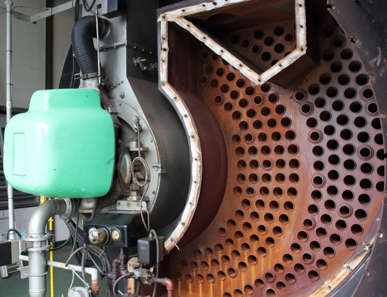
Large scale ash production adds complexity to coal combustion. The minerals listed in the table above, as well as others, possess distinct melting points that are affected when these minerals are combined. Thus, at the height of coal-fired boiler construction in the mid-20th century, the design and size of boilers were based on the type of coal to be combusted and the characteristics of the resulting ash. Depending upon the mineral combination, ash can exhibit acidic or basic chemistry, which influences fireside fouling and corrosion.
The three most common coal boiler types for power generation were the cyclone, wall-fired, scrand tangentially-fired (T-fired) design. In cyclone boilers, coal is ground to pebble size and injected into the cyclone barrels, the location of primary combustion. Most of the ash (up to 80% in some cyclone units) is tapped in the molten state from the bottom of the boiler, appropriately named bottom ash. This ash must be quenched with water prior to removal from the boiler. Wall-fired and T-fired boilers utilize pulverized coal ground into a fine powder. Combustion in these units takes place directly within the main furnace. Up to 80% of the ash departs as fly ash, with the remaining bottom ash removed as a solid.
Requirements to lower sulfur dioxide emissions led to unforeseen difficulties that plagued many of the bituminous coal units in the last century. At some plants, wet (and occasionally dry) scrubbers were installed to remove sulfur dioxide (SO₂). However, at many facilities, plant management opted for an alternative strategy, transitioning from high-sulfur bituminous coals to low-sulfur Powder River Basin (PRB) coals. As a result, this became a large source of business for the major western railroads, who began hauling millions of tons of coal to Midwestern and Eastern power plants.
The change to PRB coal in boilers designed for bituminous coal came at a significant cost, however. In addition to the much longer transportation distances, the primary issue emerged from the change in the ash characteristics. PRB ash transitions from a solid phase to a completely molten phase over a narrow temperature range, whereas the change is more gradual for bituminous coals. Additionally, though the ash content of PRB coal is relatively low, the calcium percentage is higher. These factors, and others, caused severe slagging problems in many bituminous-designed units, and employment of specialty firms to blast hard deposits with dynamite was not uncommon.
While coal is derived from the biologically and chemically altered remains of terrestrial plant life, oil originates from the remnants of marine organisms. In this process, sea creatures buried with mud and silt decompose under temperature and pressure to produce organic deposits. In this instance, however, the distinct composition of marine organisms, as opposed to vegetation, results in the formation of smaller organic molecules that are subsequently liquefied. Often, the liquid was filtered through rock formations and collected in pockets. These pockets were the sources of the “gushers” that American prospectors once found in the United States and can still be found in other areas of the world. In other instances, oil became entrapped within sedimentary formations and remained difficult to extract until the development of hydraulic fracturing technology.
Table 5 outlines some basic properties of fuel oils.
Table 5-5 – Fuel Oil Specification Ranges. Courtesy of The Babcock & Wilcox Company Company.
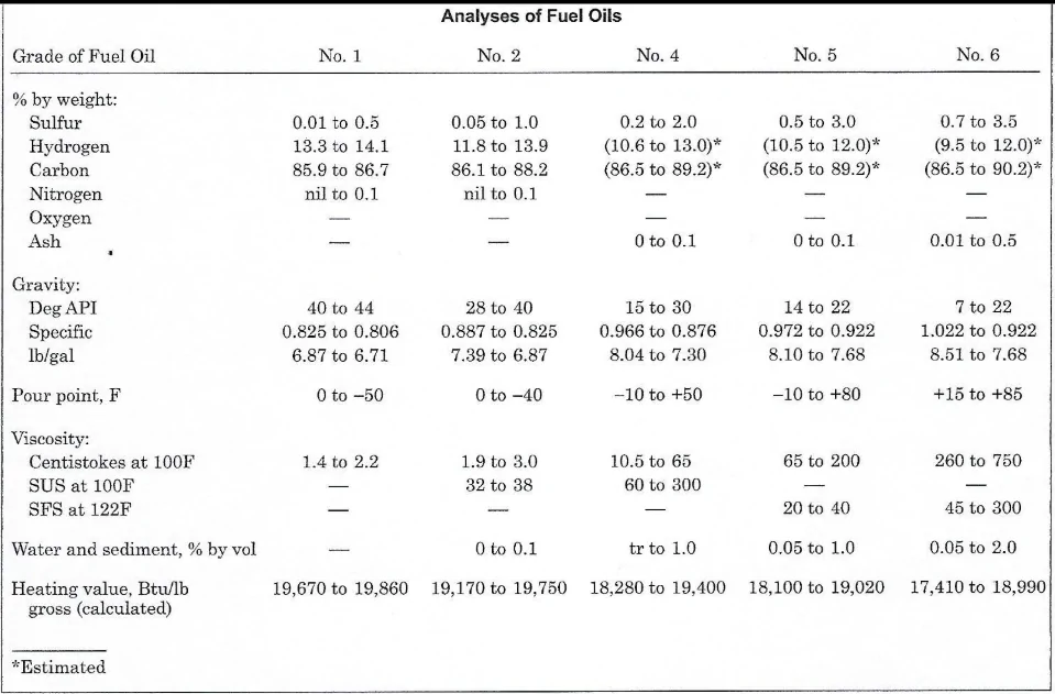
As is evident, oils become denser and more viscous moving from No. 1 to No. 6. Fuel oil No. 2 is a common fuel for light-off and warm-up of coal-fired boilers.
Natural gas is commonly found in independent pockets or associated with oil or coal fields. More recently, the development of horizontal hydraulic fracturing, or “fracking,” has opened many additional large deposits of natural gas and oil that were formerly trapped in shale sediments. The prime component of natural gas is methane (CH4), although as Table 5-6 illustrates, other hydrocarbons may be present, most notably ethane (C2H6), which is the next compound in the alkane series.
Table 5-6 – Composition of Several Natural Gas Supplies. Courtesy of The Babcock & Wilcox Company.
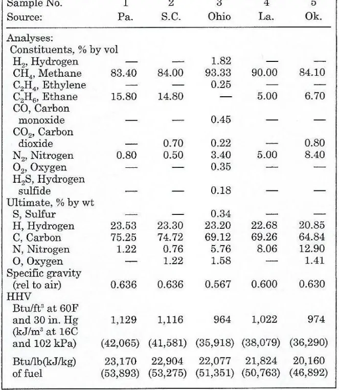
Natural gas has become the primary fossil fuel for power production, as it is easy to handle, has a pipeline infrastructure in place, burns cleanly, and produces fewer pollutants than other fuels. Of the primary fossil fuels, natural gas has the highest heating value per unit weight. This, along with the great increase in supplies produced by fracking, has led to the proliferation of combined cycle power units, some of which operate above 60% net efficiency. Because natural gas is a clean fuel as delivered, combustion products (ash, slag) are non-existent.
Solid combustion byproducts are often accompanied by their own set of difficulties. For example, furnace designs could be solely based on heat transfer considerations in the absence of ash3. The inorganic minerals present in the fuel do not combust during the combustion process. Consequently, they are either expelled from the boiler or accumulate on the internal surfaces of the boiler. In general, coal plants are designed around ash characteristics and removal requirements.
Table 5-7 outlines additional fuel analyses from coals around the United States and, for the discussion in this section, illustrates the ash chemistry of these coals.
Table 5-7
Additional Properties of U.S. Coals Including Ash Composition
Courtesy of The Babcock & Wilcox Company.
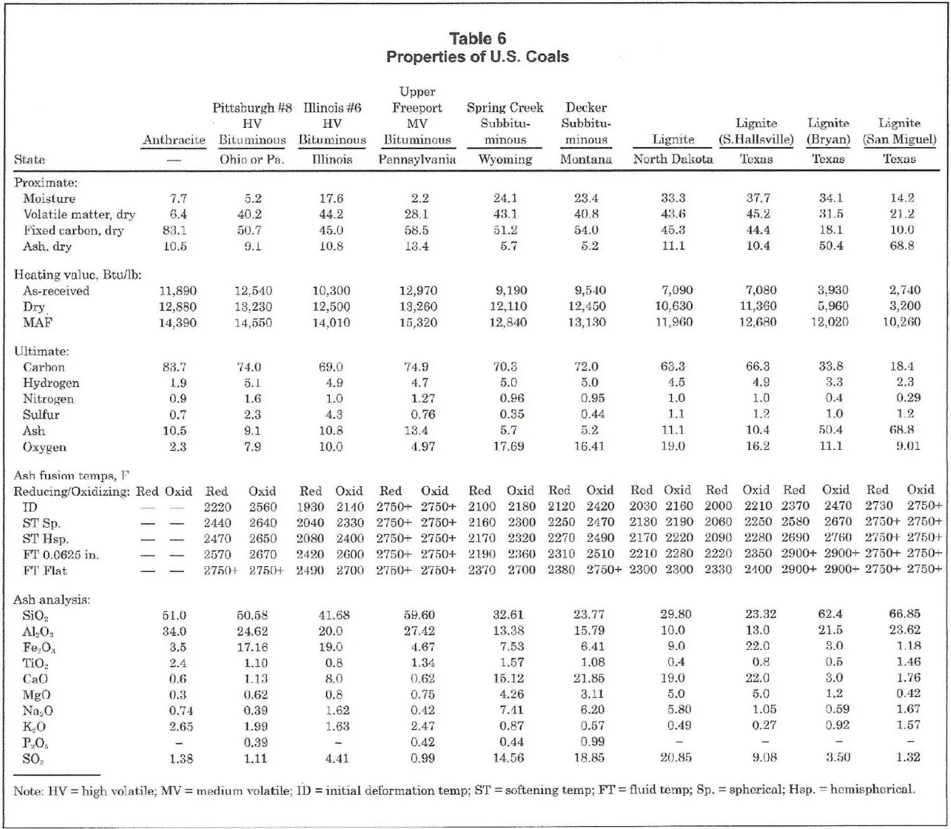
The data reveals several interesting details.
First, the ash content of the two western subbituminous coals is lower than that of all other coals, although lower ash content does not necessarily indicate less fouling.
Second, all coals contain significant amounts of silica and aluminum, which come from the complex aluminosilicates that make up much of the earth’s crust.
Third, there is the variable content of iron, the alkali metals sodium and potassium, and the alkaline earth metals calcium and magnesium. These significantly influence ash melting temperatures and other properties, which influence slagging and fouling.
Fourth are the variable sulfur concentrations. Separate from air pollution, sulfur compounds play a direct role in boiler tube corrosion.
The ash constituents are all reported as oxides. This is the standard method for reporting ash analyses, but, as shown in Table 5-5, the original minerals are typically more complex. An initial item to note from Table 5-6 is the definition of bituminous and lignitic ash. Bituminous ash has a higher concentration of ferric oxide than calcium and magnesium oxides combined. The definition of lignitic ash is the reverse; the concentration of ferric oxide is less than the combined amount of calcium and magnesium oxides.
When examining ash chemistry and its impact on boilers, it is crucial to first consider the concept of ash melting behavior, commonly referred to as fusibility. The ASTM has developed a test for determining the melting characteristics of ash. The test involves forming an ash sample into a small pyramid, subjecting it to controlled heating, and measuring deformation characteristics. The four parameters are Initial Deformation Temperature (IT), Softening Temperature (ST), Hemispherical Temperature (HT), and Fluid Temperature (FT).

Figure 5.1 Deformation characteristics of ash during heating.
These characteristics are defined as follows:
Table 5-7 shows that fusibility temperatures may change markedly with a shift from oxidizing to reducing atmospheres. Generally, this is due to the conversion of iron to various oxidation states.
This data allows an examination of slagging and fouling characteristics of ash. Slagging is the buildup of deposits on furnace walls subjected to radiant heat. Fouling is the deposition of ash residue on convective heating surfaces.
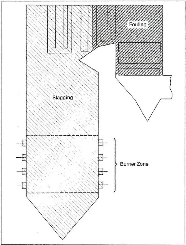
Figure 5.2 Typical regions in a boiler for slagging and fouling. Courtesy of The Babcock & Wilcox Company.
Slag formation is directly influenced by the fusibility properties of ash. The combustion zone of the boiler is the highest heat area, and ash is often molten in this region. When completely molten, ash flows readily. However, ash viscosity can often increase dramatically with just a small temperature drop. Ash particles within the IT-HT temperature range may form highly adhesive particles that bond tightly to tube walls. Heavy slagging reduces heat transfer in the waterwalls, which increases superheater and reheater gas temperatures. Slagging may extend into further reaches of the boiler if heat transfer degrades in the furnace.
Each mineral compound in ash influences fusibility. Interactions between minerals further complicate the issue.
The minerals formed during coal combustion can be categorized as either basic or acidic. If these minerals were placed individually in water, they would produce solutions that are either basic or acidic to varying degrees. The basic minerals are iron, calcium, magnesium, sodium, and potassium oxides. The acidic minerals are silica, alumina, and titanium dioxide. The ratio of basic to acidic minerals in ash significantly influences melting temperatures.
The ratio of silica to alumina also influences melting temperatures. When mixed with basic partners, silica tends to produce lower ash melting temperatures than if the acidic component was alumina.
Another important parameter is the iron/calcium ratio, where the ferric oxide (Fe2O3) portion of iron is considered. The fluxing action among iron and calcium is complex, but the general trend is that lower Fe2O3/CaO ratios tend to lower the ash softening temperature.
Dolomite is a prevalent form of limestone where calcium is significantly supplemented with magnesium. It has a similar effect with iron as simple calcium oxide. With two coals of similar base content, the one with the higher percentage of dolomite will tend to have higher fusion temperatures.
This definition was established to explain the effects of iron under oxidizing or reducing conditions. In a boiler fired with excess air at the main burners, most of the iron in the coal reacts to form Fe2O3. In a reducing atmosphere, such as in a boiler utilizing overfire air for NOx control, the iron present in the reducing zone will exhibit the presence of ferrous oxide (FeO) and potentially some metallic iron (Fe). These compounds each lower ash melting temperatures.
As silica percentage increases compared to the other fluxing agents iron, calcium oxide, and magnesium oxide, the ash viscosity increases.
Sodium and potassium lower ash melting temperatures. Alkalis are important in relation to superheater and reheater fouling, as outlined in the next section.
As is evident, a wide variety of factors influence slagging properties. It is impossible to completely predict the slagging properties of a coal, though a set of calculations for evaluating slagging potential have been developed2. Slag control efforts are apparent in boiler design. Cyclone units, which gained popularity during the 1960s, were designed to generate molten slag within the cyclone barrels and the lower sections of the boiler. The molten slag was subsequently drained in its liquid form into a water-filled slag tank. This is known as the wet bottom concept (which refers to the molten slag, not the water-filled slag tank). The ratio of bottom ash to fly ash in a cyclone unit is approximately 80% to 20%. Most pulverized coal units operate differently. The tiny coal particles burn quickly, and the fine ash residue is carried upward with furnace flow. In a properly designed system, most of the ash that contacts the furnace walls has already solidified and does not stick. In these types of units, the distribution of ash is essentially inverted, with up to 80% of the ash escaping as fly ash and approximately 20% being collected as bottom ash. Because the bottom ash does not discharge in a molten state, these are known as dry bottom units.
Fouling is most prominent in the boiler convection pass, primarily in the superheater and reheater areas. Fouling is caused by the deposition of fly ash particles on tube and duct surfaces. In the absence of furnace upsets, the ash particles entering the convection pass are expected to remain in solid form and, on their own, should not exhibit a significant tendency to adhere to the equipment. However, combustion generates volatile alkali compounds of sodium and potassium that condense on tube surfaces and ash particles, giving them much stronger adhesion tendencies.
The concentration of sodium and potassium in the flue gas is related to how these two elements are bound within the original fuel. Sodium and potassium that are combined with silicates tend to remain stable throughout the process. However, a percentage of the alkalis exist as simple salts, primarily chlorides, or are organically bound in the coal. These “active” alkalis vaporize during the combustion process and form the oxides Na2O and K2O. The relatively lower temperatures in the convective pass of the boiler allow the alkalis to condense.
Generally, the bulk of active alkalis exist as chloride salts, so a measure of coal chlorine content is a reasonable guideline to determine the relative fouling potential.
Table 5-8 – Fouling Potential Related to Coal Chlorine Content and as Converted To Volatile Sodium
|
Fouling Potential |
Chlorine (%) |
Equivalent Sodium (%) |
|
High |
>0.5 |
>0.33 |
|
Medium |
0.3 |
0.2 |
|
Low |
<0.1 |
<0.07 |
Another important relationship between sodium and fouling is that a greater active sodium content increases the strength of ash deposits. Figure 5.3 below shows that this is true for both bituminous ash and lignitic ash coals. In both cases, but particularly for lignitic ash, the ash strength increases significantly with increasing sodium oxide content.
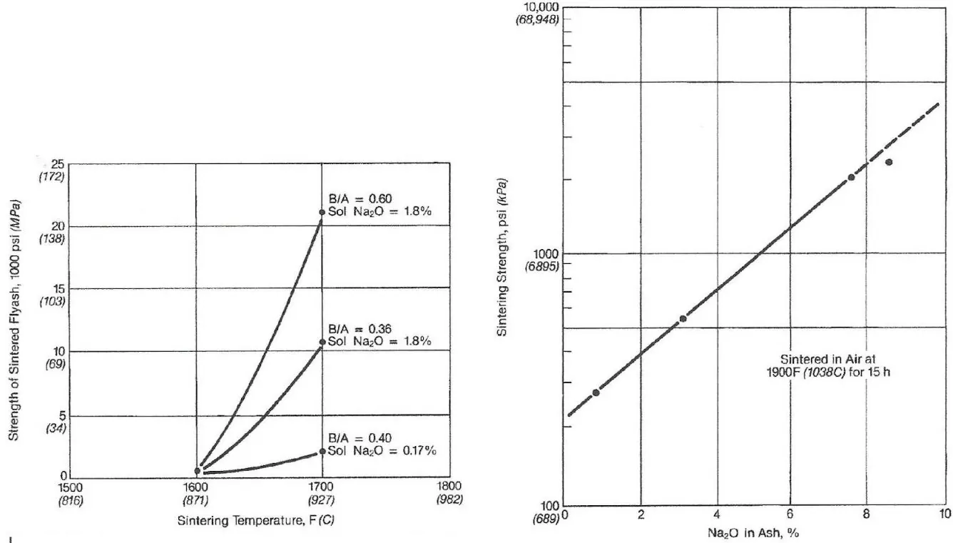
Figures 5.3a and b. Influence of active sodium on the sintering strength of fly ash deposits. Courtesy of The Babcock & Wilcox Company.
Greater sintering strength equates to increasing difficulty in removing deposits with sootblowers. Further, sintering strength can be greatly reduced by washing the coal to reduce the active alkali concentration.
Fouling of convective pass equipment and surfaces causes a number of problems. Buildups on superheater tubes reduces heat transfer efficiency, but buildups also cause channeling or “laning” of the flue gas. This increases linear velocity through open areas, which may lead to an increase in erosion on other tubes. It is not uncommon for tube failures to be caused by ash erosion. Excessive ash buildups between superheater pendants may cause bridging of material between pendant sections. Slag and ash deposits in the upper sections of the radiant portion of the boiler may break loose and damage or puncture furnace floor tubes when they strike bottom.
The accumulation of ash deposits in the convective pass can also have adverse effects from a corrosion perspective. As ash deposits build up, volatile alkalis and sulfur trioxide (SO3) produced during combustion diffuse through the ash to initiate corrosion reactions. Figure 5.4 illustrates one example of the morphology of a coal ash corrosion deposit.
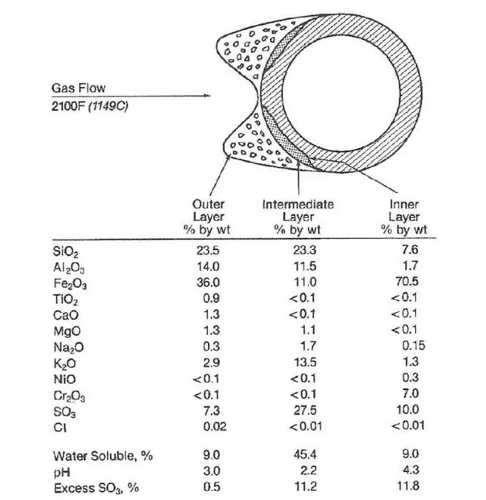
Figure 5.4 One example of the morphology of an ash deposit on a stainless-steel superheater tube. Courtesy of The Babcock & Wilcox Company.
Outlined below are two reactions that illustrate how deposits can accumulate and lead to the corrosion of tube metal:
| 3K2SO4 + Fe2O3 + 3SO3 → 2K3Fe(SO4)3 | Eq. 1 |
| K2SO4 + Al2O3 + 3SO3 → 2KAl(SO4)2 | Eq. 2 |
Whereas sodium is the prime culprit in deposit formation and strength, potassium appears to be the chief alkali initiating corrosion reactions. In this example, three layers have developed. The first is an outer layer, which is mostly fly ash. The intermediate layer is white- to yellow-colored and shows a marked increase in potassium and SO3 concentration. As the figure illustrates, this layer has replaced original tube metal. The inner layer is a thin black band located at the tube surface and is the site of active corrosion. Iron content is high because of its proximity to the base metal, and the compounds within this layer include iron sulfides and sulfates.
In contrast to these examples of high-temperature fouling and corrosion, low-temperature corrosion of air heaters and outlet ducts will occur if the flue gas temperature is allowed to drop below the acid dew point. A small amount of the sulfur combusted in the boiler converts to SO3. If the temperature drops too low at the back end of the boiler, the SO3 will combine with moisture to produce sulfuric acid, H2SO4. Although the sulfuric acid concentration may be minimal, the liquid is quite corrosive to carbon steel. Exit gas temperatures must be maintained above the dew point temperature through the boiler backpass (and electrostatic precipitator if the unit has one) to prevent corrosion.
Oil contains significantly lower mineral content than coal, resulting in less complex oil ash deposition problems. Typically, oil ash does not cause corrosion of waterwall tubes. Because of the low-melting ash despoits, the superheater and reheater are often the problematic areas. Additionally, as with coal combustion products, back-end corrosion due to acid dew point corrosion is a possibility.
The primary cause of ash corrosion is vanadium, which originates from soil minerals and the organic matter that decomposed to form oil. Oils may contain virtually no vanadium to almost 400 parts-per-million (ppm). Vanadium released in combustion forms several oxides, V2O3, V2O4, and V2O5. These oxides combine with alkali salts to form low-melting compounds that accumulate on tube surfaces. Equation 3 illustrates a typical reaction.
| Na2SO4 + V2O5 → 2NaVO3 + SO3 | Eq. 3 |
The melting point of NaVO3 is 1,165°F (629°C). Sodium-vanadium compounds with low melting points exhibit direct corrosive effects on steel, and the corrosion rate accelerates with increasing metal temperature. Control methods include selecting low-vanadium oil, designing boilers to reduce metal temperatures, implementing effective sootblower designs to keep tubes clean, and using chemical additives to manage corrosion.
Chemical addition to the fuel feed is sometimes utilized to reduce slagging and fouling. Common additives include alumina and magnesium compounds like magnesium oxide. These compounds modify the chemistry and melting point of ash deposits, making them less adherent and more easily removable through sootblowing. Additive feed is most common at plants that were switched from bituminous to PRB coals.
Although decarbonization efforts continue to diminish the fossil fuel power industry, specifically coal plants, many will temporarily remain to ensure grid stability. Fireside chemistry is complex, where changes in fuel source, operational conditions, and other factors can lead to slagging, fouling, and corrosion. Most plants now have sophisticated instrumentation and control room computer displays that allow operators to monitor conditions throughout the boiler and downstream flue gas path. This technology is critically important for consistent and reliable operation, particularly in this era when even large units must regularly cycle up and down in load.
Appendix 5-1
The first national air pollution legislation in the United States was the Clean Air Act of 1963. This initial legislation was designed to guide the states in dealing with air pollution control issues. Additional regulations were proposed and passed later in the 1960s, but the turning point came with the establishment of the Environmental Protection Agency (EPA) in 1970 and the subsequent passage of the Clean Air Act Amendments (CAAA) in December of that year.
The EPA, under Congressional authority, was tasked with developing National Ambient Air Quality Standards (NAAQS), which, with passage of the 1990 CAAA, evolved into the stipulation that each state would be responsible for meeting the NAAQS for six criteria air pollutants; nitrogen oxide, sulfur dioxide, carbon monoxide, ozone, particulate matter, and lead. This section examines three of the items from this list: nitrogen oxides, sulfur dioxide, and particulate matter.
The following schematic outlines the principal methods by which these pollutants are removed from coal plant flue gas.
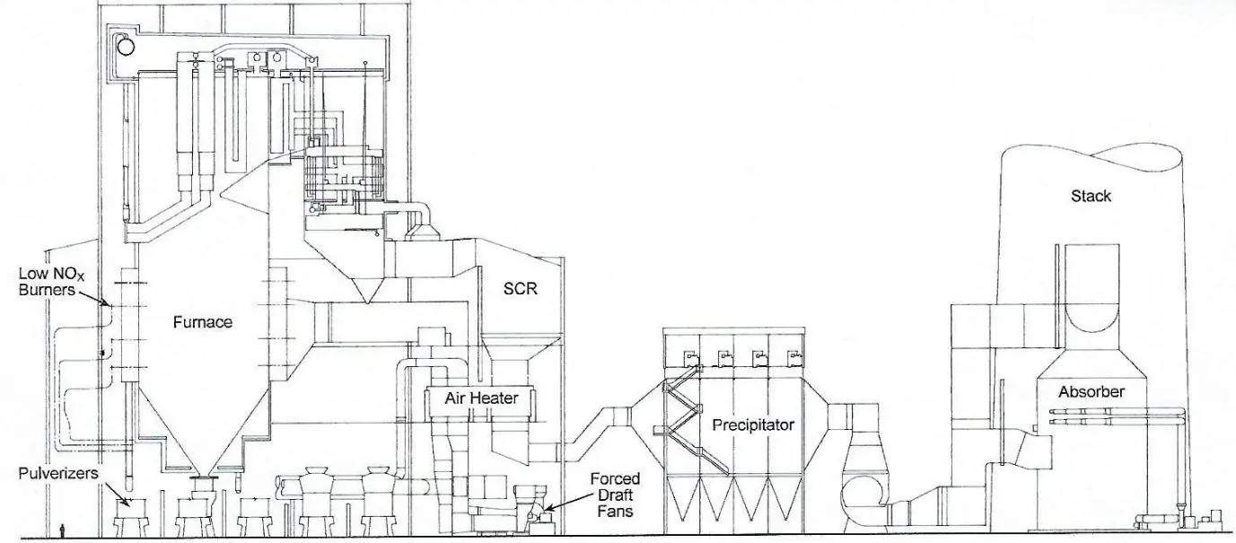
Figure 5.1.1 Outline of primary air pollution control devices in a coal-fired boiler. Courtesy of The Babcock & Wilcox Company.
The progression is:
NOx is a primary element of acid rain and contributes to ground-level ozone formation, particularly in large cities where atmospheric pollutants become concentrated. The term NOx is all-inclusive, as fossil-fuel combustion produces several oxides of nitrogen, most notably nitrogen oxide (NO) and nitrogen dioxide (NO2). A typical ratio of NO to NO2 produced in the furnace is 9 to 1. In plants equipped with a sulfur dioxide scrubber, NO2, which is water soluble, will wash out of the flue gas. However, NO is only slightly soluble, and because it usually makes up about 90% of the NOx, scrubbing is not an effective treatment process.4
When nitrogen oxides enter the atmosphere, several problems arise. NOx participates in a series of complex photochemical reactions with volatile organic compounds that produce ground-level ozone (O3). While the high level of ozone in the earth’s atmosphere protects us from harmful solar radiation, ground-level ozone causes respiratory problems, especially in the very young, the elderly, smokers, asthmatics, and people with other lung problems. Upon release from the boiler, much of the NO converts to NO2, which, like its SO2 counterpart, combines with water to form an acid, in this case nitric acid (HNO3).
Nitrogen oxides produced during coal combustion are generally grouped into two categories: thermal NOx and fuel NOx. Thermal NOx is generated by the high heat of combustion and results from the reaction of atmospheric nitrogen (N2) and oxygen (O2). Even in pulverized coal units, thermal NOx may only account for a quarter of all NOx emissions, as thermal NOx formation does not become notably pronounced until temperatures reach 2,800ºF. A well-known technique to reduce thermal NOx is flue gas recirculation, in which a portion of the flue gas is recycled to the furnace inlet. This lowers furnace temperatures slightly, but enough to significantly limit thermal NOx production.
Fuel NOx is a different story. Most nitrogen in coal is organically bound to carbon atoms, and these bonds are much easier to break than those of N2. As the coal combusts, individual nitrogen atoms are released. As opposed to molecules, nitrogen atoms are very reactive and quickly attach to oxygen.
Control of nitrogen oxide formation and discharge generally falls into two categories: concurrent combustion control and post combustion control. Low-NOx burners (LNB) and overfire air (OFA) belong to the first category. The detailed chemistry of LNB and OFA methodology is complex, but the basics are as follows. When coal or any other fossil fuel is burned with an excess of oxygen, combustion of the carbon content proceeds to completion, as expressed as below:
| C + O2 → CO2 | Eq. 1 |
Energy-wise, this reaction is favorable and gives off substantial heat. When sub-stoichiometric amounts of oxygen are introduced into the process, a portion of the coal undergoes partial oxidation to carbon monoxide, potentially leaving some unburned carbon:
| C + ½O2 → CO | Eq. 2 |
Carbon monoxide seeks oxygen atoms to complete the reaction to carbon dioxide. When insufficient oxygen is available, the molecules will take oxygen from nitrogen oxides, which is the basis behind LNB and OFA. The fuel is initially combusted in an oxygen-lean environment to allow the formation of reduced carbon species. These reduced carbon compounds strip oxygen from NOx and allow nitrogen atoms to combine into N2. The chemistry becomes complex because of the high number of molecular interactions that take place, even during the brief time that the molecules are at the burner front. A nitrogen oxide molecule may give up its oxygen atom(s) to carbon, only to combine with another oxygen. This process may happen repeatedly before the nitrogen atom meets another nitrogen atom to form N2. Many intermediate chemical species are produced during combustion, and the interactions that eventually reduce NOx levels are rather complex. The remaining air for combustion is injected at a higher elevation in the furnace to convert the residual unburned carbon and carbon monoxide to CO2.
With OFA, the area of reducing conditions between the burners and the OFA ports represents a frequent problem. During conventional combustion, excess air is injected with the fuel to ensure most of the carbon in the coal burns to completion. The excess air establishes an oxidizing atmosphere in the furnace where the boiler tubes develop an oxide coating. In systems utilizing OFA, the combustion products located between the main burners and the OFA feed points contain reducing compounds, including sulfides. These may react with the metal in tube walls to form iron sulfides that are not protective like their counterpart oxides. Corrosion and spalling of tube material can occur in the reducing environment between the burners and OFA injection nozzles.
The combination of low-NOx burners and OFA has proven capable of lowering NOx emissions to levels close to 0.15 lb./MBtu (0.064 kg/106 kJ). A common supplement to LNB/OFA is post combustion control with selective catalytic reduction (SCR).

Figure 5.1.2 Generic diagram of an ammonia injection system and catalyst layers for a SCR system.
Typical SCR reactions are illustrated in the following two equations.
| 4NO + 4NH3 → 4N2 + 6H2O | Eq. 3 |
| 2NO2 + 4NH3 + O2 → 3N2 + 6H2O | Eq. 4 |
Ammonia reacts with NOx to generate elemental nitrogen, with the reactions taking place in fixed catalyst beds in the flue gas stream. A variety of materials are viable to serve as SCR catalysts, most commonly titanium dioxide, vanadium pentoxide, precious metals, and zeolites (aluminosilicates). The ideal operating range of the transition metal (titanium, vanadium) catalysts is generally 450ºF to 850ºF, while the zeolites operate at a higher temperature range of approximately 850ºF to 1,050ºF. The most common structural configuration is a block-type catalyst manufactured in honeycomb configuration.
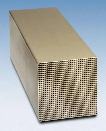
Figure 5.1.3 Block of honeycomb SCR catalyst. Courtesy of The Babcock & Wilcox Company.
SCR introduces several potential complicating factors to plant operations. An excess of ammonia must be added to reduce NOx to low levels. A portion of the ammonia will undergo oxidation to nitrogen on the catalyst bed; however, some ammonia will pass through the bed unreacted. This phenomenon is referred to as ammonia slip. Ammonia is considered a regulated substance for accident prevention, as it can react with other pollutants to form fine particulate matter.5 A common limit for ammonia discharge in flue gas is 2 parts per million. These limits are important to maintain fly ash quality, particularly if that ash is subsequently utilized as an additive in construction materials.
SCR catalysts gradually degrade over the life of the material. The extent of catalyst poisoning will vary based on the catalyst’s composition and its content of arsenic, phosphorus, and other elements or compounds. As would be expected, the lead (first) catalyst bed exhausts first. A common replacement method is to move all beds one place forward and put the new catalyst bed at the trailing location after the lead bed is removed.
The reaction of ammonia with sulfur trioxide in the flue gas results in the formation of ammonium sulfate [(NH4)2SO4] and ammonium bisulfate (NH4HSO4). Both compounds contribute to fouling and corrosion of downstream equipment, particularly air heaters, with ammonium bisulfate being especially problematic. Another problem with ammonia derives from its’ storage on plant grounds. The EPA classifies anhydrous ammonia and aqueous ammonia at or above 20 percent concentration as regulated toxic substances. Consequently, urea conversion has become more common to generate ammonia for SCR systems.
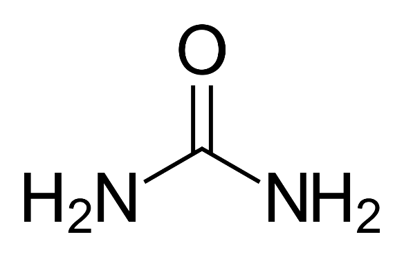
Figure 5.1.4 Chemical structure of urea.
Urea is an agricultural chemical that can be hydrolyzed to produce ammonia and carbon dioxide. Hydrolysis systems at power plants allow ammonia to be generated per demand without storage of hazardous ammonia.
Particulate matter was one of the first pollutants from coal-fired boilers to be recognized as problematic. Boiler type significantly influences particulate formation. In traditional cyclone boilers, most of the ash (up to 80%) exits as bottom ash in a molten state, which is then solidified in a water-filled slag tank. Fly ash volume is relatively low in cyclone boilers. Few of these units remain because of their age, low efficiency, and propensity to produce large amounts of NOx. In pulverized-coal units, where up to 80% of the ash may exit with the flue gas, particulate concentrations are quite high. All plants require capture of at least 99% of these particulates. Two major processes, electrostatic precipitation and fabric filter collection, have been popular for particulate control.
A schematic of an electrostatic precipitator (ESP) is included below.
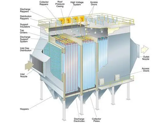
Figure 5.1.5 Schematic of a common ESP. Courtesy of The Babcock & Wilcox Company.
An electric potential is induced between the collecting plates and solid electrodes (or wires in older units), where a negative potential is applied to the electrodes and a positive potential to the plates. As the flue gas passes through the precipitator, the particles develop a negative electrical charge from the electrodes. The particles are then attracted to and accumulate on the plates. The plates are periodically shaken (rapped) by mechanical vibrators, causing the ash to fall to the bottom of the precipitator where it is collected in hoppers for discharge through the ash disposal system.
To slow the linear velocity of the gas to ensure the particles have sufficient time to develop a charge, the ESP is much larger than the entry flue gas duct. A typical entering velocity may be 60 feet per second, while flow through the precipitator may only be 4–5 feet per second. ESPs consist of a series of cells where ash removal efficiency is around 75% per cell. When combined in series, it is possible to see overall efficiencies of 99%. The distance between collecting plates in an ESP may range from 9–16 inches, with the negative electrode evenly centered between collecting plates.
Numerous factors influence precipitator performance, including:
Mechanical factors affecting performance:
Operational factors affecting performance:
Another widely used particulate removal technique is fabric filtration, commonly known as baghouses. In this process, the flue gas passes through a fine mesh fabric filter and particulates collect on one side of the filter. Periodic vibrations dislodge the ash, and it falls to hoppers for collection. Figure 5.1.6 shows the generic outline of a popular type, the pulse-jet fabric filter.
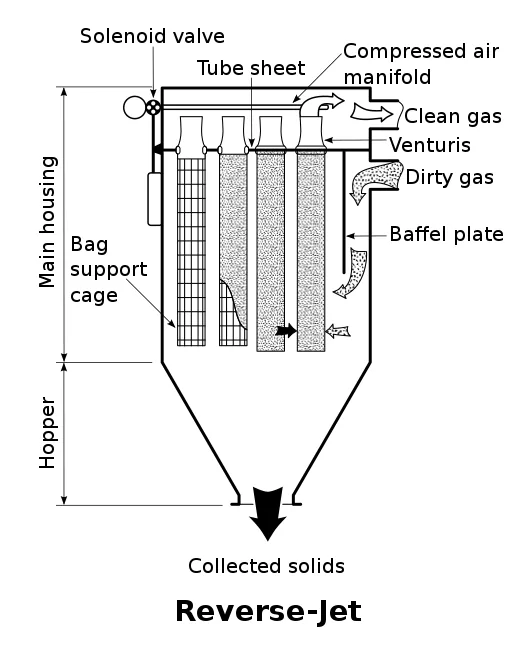
Figure 5.1.6 Basic schematic of a pulse-jet fabric filter particulate control device.
The bags are mounted on wire frames within the vessel. Flue gas enters from the side, is deflected by, and flows around a baffle plate, then passes through the bags. Fly ash remains on the exterior of the bags as the flue gas exits the top of the vessel. Periodically, a jet of air is blown through the bags to dislodge the ash, which falls to hoppers below. Baghouses typically feature several compartments, each containing rows of filters.
Redundancy is incorporated by automatically isolating individual compartments from the flue gas stream, followed by pulse cleaning. This prevents the ash from being re-entrained in the flue gas. Cloth-to-air ratio, filter diameter and length, and flue gas temperature are each factors that baghouse design engineers must consider. Progressive improvements in cloth design allow baghouses to operate at temperatures of up to 500ºF. Though such materials can withstand high temperatures; they are still susceptible to fires if unburned carbon accumulates in the cloth. Baghouse fires can be extremely dangerous, in large part because opening access doors to combat the fire introduces additional oxygen. Additionally, when water is sprayed on the fire, burning coal particles tend to float. Because of this, foam or CO2 suppression systems are more suitable to combat baghouse fires.
As the baghouse operates as a filtering medium, unlike the electrical charge process of an electrostatic precipitator (ESP), its removal efficiency remains consistent across various ash properties. This is a prominent factor that has increased baghouse popularity vs. ESPs.
Upon the announcement of the original Clean Air Act (Air Quality Act, 1967) regulations and subsequent amendments in the 1960s and 1970s, many plants were required to install scrubbers to remove sulfur dioxide from boiler flue gas, particularly if the desire was continued use of Eastern and Midwestern bituminous coal.
Initially, the most popular method was wet-limestone scrubbing. A generic flow diagram of a spray-type, wet-limestone scrubber is provided below.
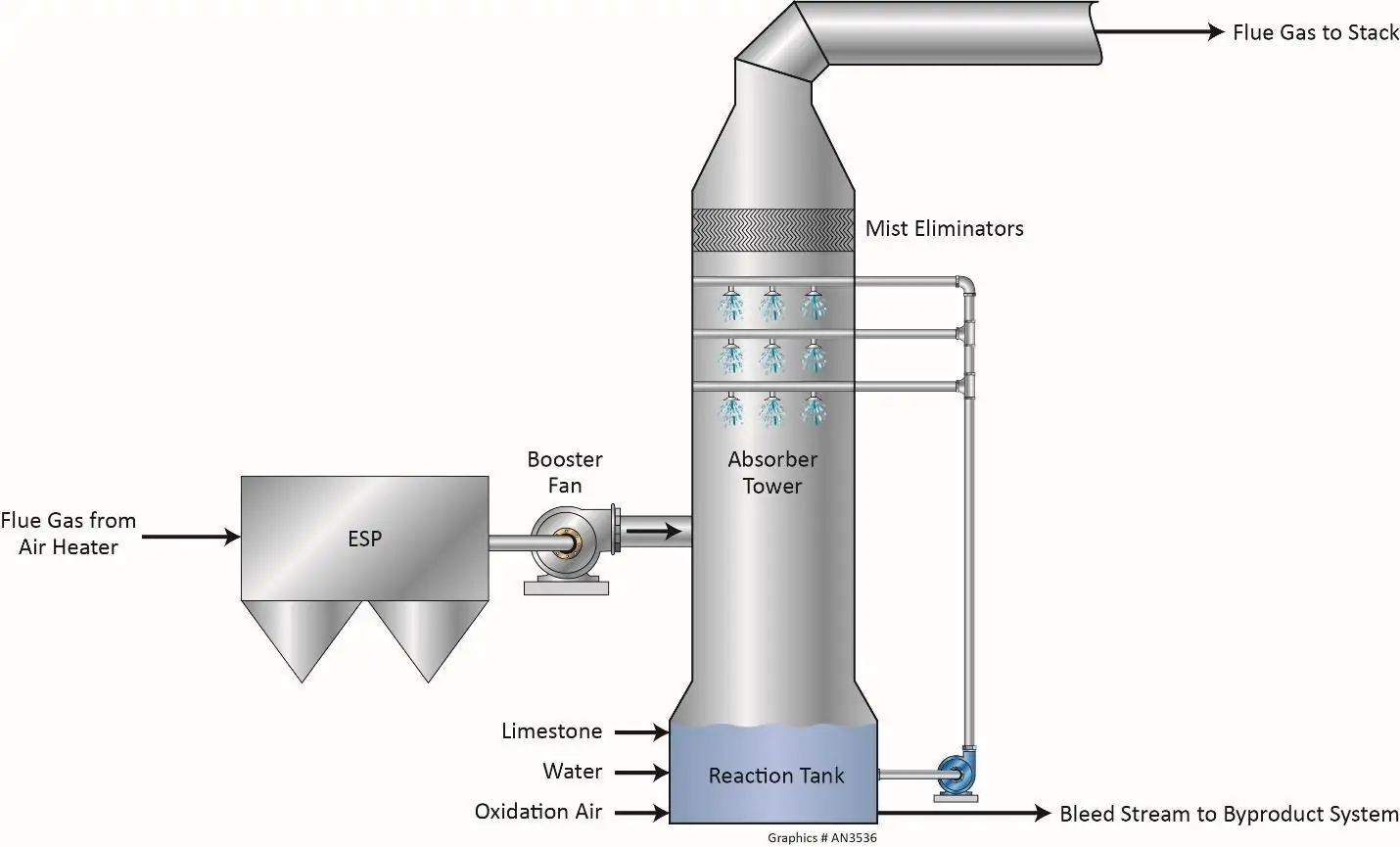
Figure 5.1.7 General diagram of a spray-type wet-limestone, forced-air oxidation scrubber.
This process exemplifies an aqueous acid-base chemistry reaction implemented on an industrial scale. Unlike most laboratory experiments, however, both the acid and the base do not initially exist in liquid form. SO2 is a gas and limestone is a solid, thus additional steps are required to induce and maximize the chemical reactions.
Sulfur dioxide is first absorbed into the liquid phase as it contacts the slurry sprays.
| SO2 + H2O ⇌ H2SO3 | Eq. 5 |
Some theoretical chemists contend that true H2SO3 does not exist, asserting instead that SO2 retains its molecular character and is surrounded by water molecules. However, when SO2 is added to water, the pH drops, which indicates that Eq. 5 is correct and the following dissociation reaction is accurate.
| H2SO3 ⇌ H+ + HSO3– ⇌ H+ + SO32– | Eq. 6 |
Another argument for the formation of H2SO3 and its dissociated products, bisulfite (HSO3–) and sulfite (SO32–) ions, is based on the observation that calcium carbonate (CaCO3), the principal component of limestone, is only slightly soluble in water but will dissolve almost completely in well-designed scrubbing systems.
| CaCO3 + H+ → Ca2+ + HCO3– | Eq. 7 |
Combining Eqs. 5, 6, and 7 illustrates the fundamental scrubbing process.
| CaCO3 + 2H+ + SO32– → Ca2+ + SO32– + H2O + CO2↑ | Eq. 8 |
In the absence of any other reactants, calcium and sulfite ions will precipitate as a hemihydrate, where water is included in the crystal lattice of the scrubber byproduct.
| Ca2+ + SO32– + ½H2O → CaSO3·½H2O↓ | Eq. 9 |
Proper operation of a scrubber is dependent upon the efficiency of the above-listed reactions. pH control with reagent feed is particularly important. Many wet-limestone scrubbers operate at a solution pH of around 5.6–5.8. An overly acidic scrubbing solution hinders the transfer of SO₂ from gas to liquid. Conversely, if the pH rises to 6.0 or higher, it indicates an overfeed of limestone.
Oxygen in the flue gas significantly influences chemistry. Aqueous bisulfite and sulfite ions react with oxygen to produce sulfate ions (SO42–).
| 2SO32– + O2 → 2SO42– | Eq. 10 |
Approximately the first 15 mole percent of sulfate ions co-precipitate with sulfite to form calcium sulfite-sulfate hemihydrate [(0.85CaSO3·0.15CaSO4)·½H2O]. Any sulfate above the 15 percent mole ratio precipitates with calcium as gypsum (CaSO4·2H2O).
| Ca2+ + SO42– + 2H2O → CaSO4·2H2O↓ | Eq. 11 |
Scrubber chemistry control offers challenges, particularly in spray towers that have internal devices, like packing, to enhance gas-liquid contact. Operational experience has demonstrated that maintaining a fully oxidized state (with no calcium sulfite-sulfate hemihydrate in the scrubbing slurry) or a fully non-oxidized state (with no gypsum in the slurry) minimizes the scaling of internal scrubber components. If the slurry is partially oxidized, the solution may hover around the calcium sulfate saturation point, which can lead to buildups of tenacious gypsum. The handling characteristics and commercial value of the solid are additional factors that influence the choice between an oxidized or non-oxidized byproduct. Calcium sulfite-sulfate hemihydrate is a soft material that tends to retain water, but it has little value as a chemical commodity. For this reason, most scrubbers are equipped with forced-air oxidation systems to drive Eqs. 10 and 11 to completion. A properly designed oxidation system will convert all sulfite to sulfate.
Preparation of the product for sale or dry disposal requires drying on a vacuum drum or belt filter, often combined with a freshwater wash to remove dissolved chlorides. Forced oxidation typically results in the formation of flat gypsum crystals that dewater efficiently. This process yields a cake-like material with a free moisture content ranging from 10% to 15%.
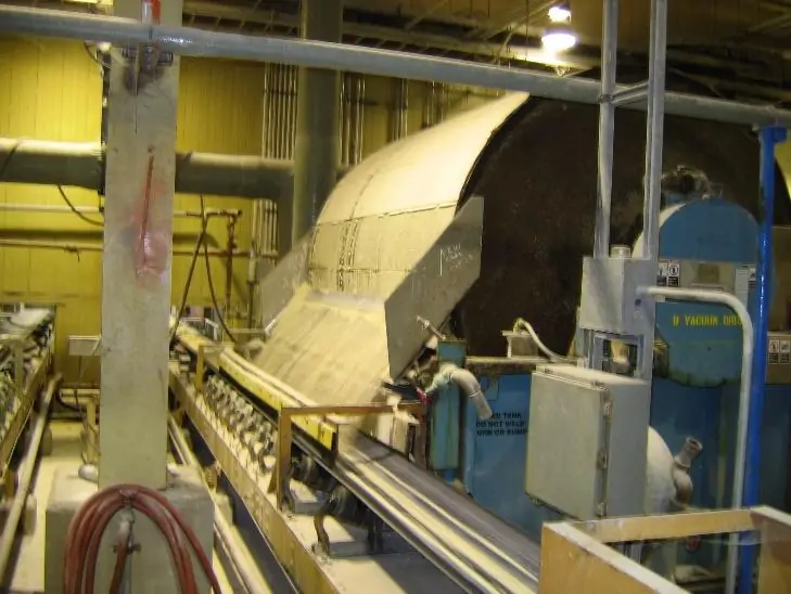
Figure 5.1.8 A rotary drum vacuum filter in operation removing gypsum “cake.” Photo courtesy of City Water, Light & Power.
The drum in Figure 5.1.8 has an internal, mechanically applied vacuum. As the drum rotates through the slurry byproduct in the vat below, the solids adhere to the filter cloth. Meanwhile, the liquid passes through the filter cloth for either collection and reuse in the scrubber or disposal. The drum rotates counterclockwise in the view show, however, not shown is a freshwater wash header on the far side located just above the vat. The water spray reduces the chloride content of the gypsum to less than 200 mg/L, which is a requirement from the wallboard manufacturer. In some cases, the manufacturer may specify a chloride limit of 100 mg/L, which may require additional washing.
When the sale of byproducts is not feasible, forced oxidation remains the preferred method due to the straightforward handling of gypsum compared to inhibited or partially oxidized materials. Dried gypsum can easily be loaded into dump trucks for disposal in a landfill.
If the limestone reagent reacts poorly in the system, overfeed is required for adequate SO2 removal, resulting in excess reagent usage. Factors that influence utilization include limestone quality and reactivity, limestone grind size, residence time of the reagent within the scrubbing system, and performance of slurry separation devices.
The grind size of limestone has always been a critical factor in determining the efficiency of flue gas desulfurization (FGD) processes. In early scrubber designs, specifications often required that only 70% of the ground limestone pass through a 200-mesh screen (79 divisions per cm), as determined by laboratory testing. However, it quickly became apparent that a finer grind was necessary to ensure the maximum scrubbing efficiency. The guideline evolved to, in many cases, 90% through a 325-mesh screen (128 divisions per cm). The finer grind increases the surface area of the limestone by nearly two-thirds.
The standard method for grinding limestone involves mixing the raw material with water in large ball mills. These mills are horizontal, rotating cylinders lined with rubber and filled with thousands of iron balls. The continuous action of the balls crashing against one another grinds the stone. Typically, the raw slurry from the ball mills contains too many coarse particles, so the discharge is routed through a bank of hydrocyclones, as illustrated in Figure 5.1.9.
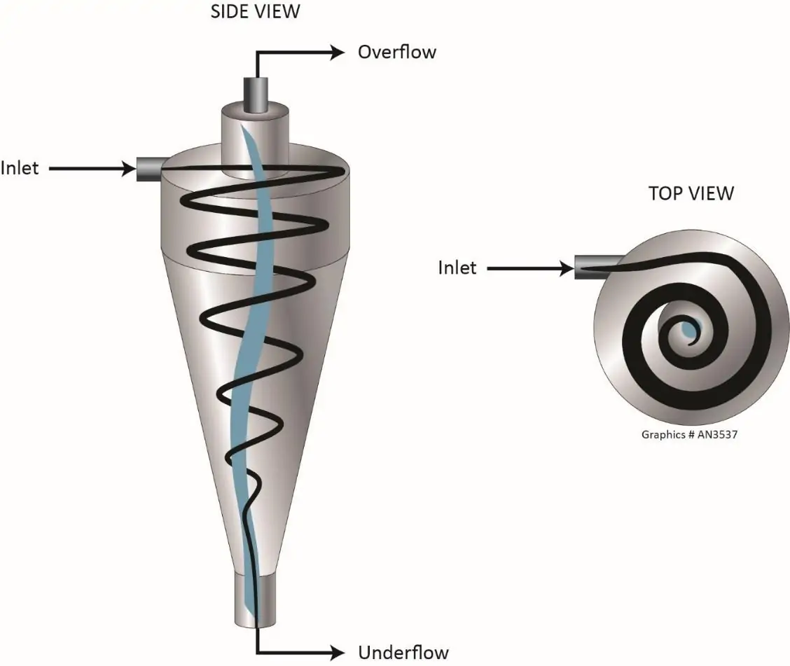
Figure 5.1.9 Hydrocyclones for limestone particle classification.
Limestone slurry enters these stationary devices in a tangential opening near the top. The design imparts a centripetal action to the slurry, forcing lighter and more reactive limestone particles through the overflow to the scrubber, while heavier particles exit through the underflow and are routed back to the ball mills. Hydrocyclones are equipped with vortex finders, similar to orifice plates, on the overflow and underflow lines. This design allows for simple filter changes to adjust the particle size exiting each port.
The chemical makeup of the reagent has a large influence on scrubber efficiency. Limestones containing 94% or more calcium carbonate are typically quite reactive, given proper grind size. However, not all plants are located near high-quality sources. Often, a stone may contain over 90% total carbonate, with 10% or more present as dolomite (MgCO3·CaCO3), where magnesium is bonded with calcium in the crystal lattice. While pure MgCO3 dissolves quickly in scrubber solutions and provides liquid alkalinity, dolomite is rather non-reactive and tends to pass through the system untouched.
Issues with low-reactivity limestone or high SO2 content in the flue gas may be resolved with the use of chemical additives to boost alkalinity. Adipic acid (hexanedioic acid), depicted in Figure 5.1.10, was once a favored organic additive, along with the less refined dibasic acid (DBA), a blend of adipic, glutaric, and succinic acids.

Figure 5.1.10 Structure of adipic acid.
These chemicals increase the liquid phase alkalinity and provide buffering to the slurry liquor. However, cost and availability have been problematic in recent years, specifically in the United States. An alternative organic acid formulation offered by ChemTreat, which has demonstrated significant limestone reactivity enhancement, is now available. An indicator of the improved efficiency of this chemistry vs. older technologies is shown in the following graphs.
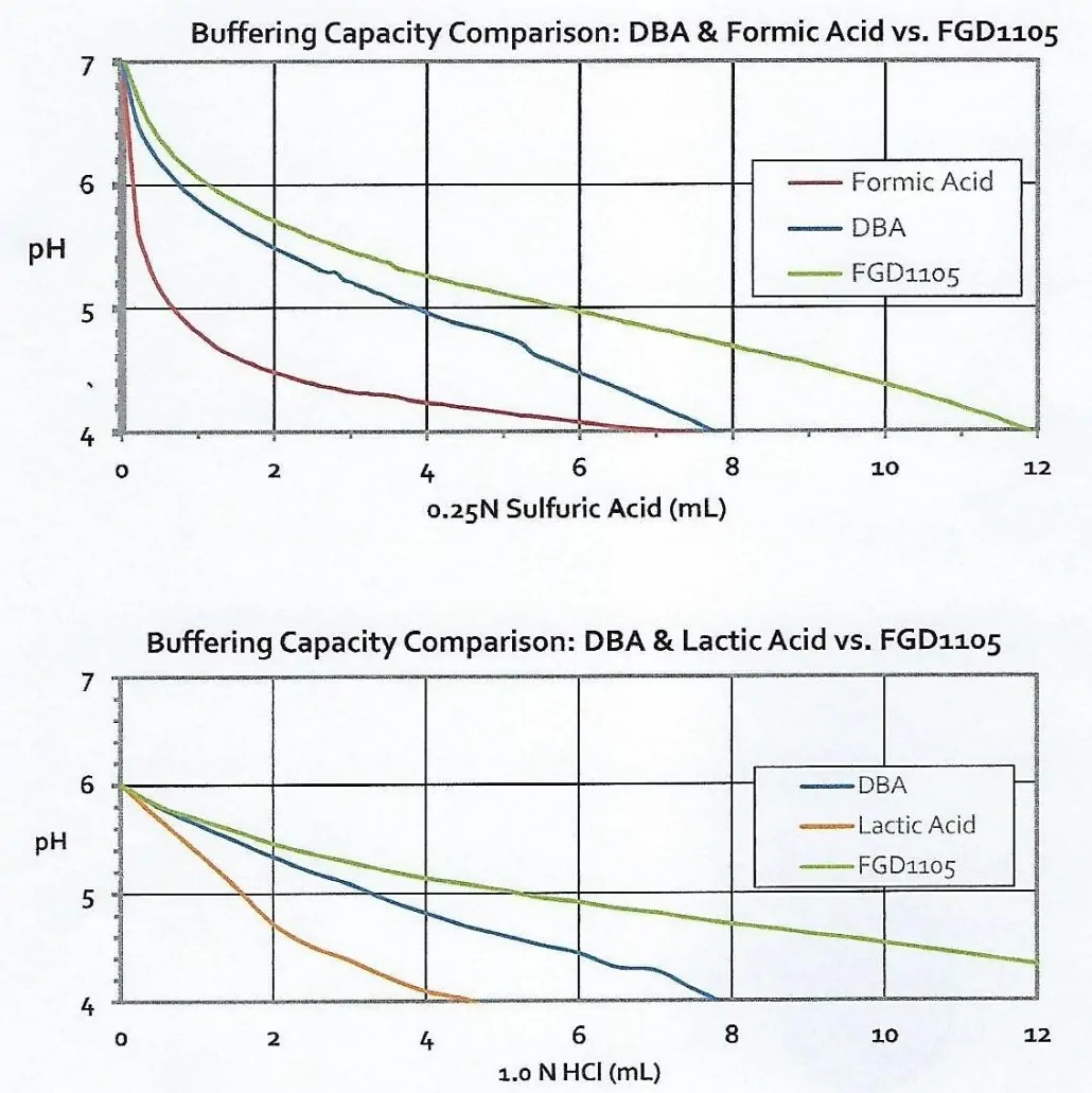
Figures 5.1.11a and b A comparison of buffering capacities of scrubber enhancement chemicals.
The product has a noticeably higher buffering capacity than DBA when titrated with both sulfuric and hydrochloric acids, and a much higher capacity than the other major alternatives, formic and lactic acids. Buffering capacity is a critical property of these products.
Correct use of an additive can potentially contribute to plant savings through improved limestone utilization and more efficient scrubbing. It may also provide more flexibility in coal source choice by allowing coals with higher sulfur content to be utilized, as opposed to lower sulfur coals that must be transported long distances.
The presence of troublesome trace concentrations of manganese and iron is another factor that can influence limestone performance, though it appears most often in lower quality stones. Prior comprehensive testing of different limestones indicated that iron was responsible for two major issues: iron catalyzed scale formation in the scrubber towers, and the generation of very fine iron oxide particulates that fouled vacuum filter cloth. Care is necessary in the selection and use of limestones.

The design of many modern systems greatly minimizes scale formation. Spraying technology has improved for scrubber applications, and open spray towers are common. Nozzle design and alignment are critical in these systems, as droplet size and spray patterns must be optimized to provide the best contact and to prevent channeling of the flue gas. Nozzles should also be designed to minimize plugging. Materials like solid chunks of scale or failed rubber pump linings can readily clog nozzles, and despite the best design efforts, some plugging may still occur.
Particulate removal with mist eliminators is another issue of importance with spray tower systems. Without adequate protection, small slurry particles will entrain with the flue gas and flow out of the scrubber. Excess particulate emissions can foul downstream components and cause opacity excursions at the stack. Demisters typically consist of chevron-vane packing, situated at the top of scrubber towers. As the flue gas passes through the vanes, the particles impinge on the blades and stick. Regular washing with clear water is a requirement to prevent severe buildups of solids on the vanes. While washing does not have to be continuous, it must be regular. Measurements of differential pressure around the mist eliminators, or other internal components, are necessary to monitor deposit buildups.
A smaller number of wet scrubbers were built with lime as the reactant. Lime (CaO) is produced by the calcination of limestone in kilns.
| CaCO3 + heat → CaO + CO2↑ | Eq. 12 |
For many industrial applications, the lime is hydrated before delivery to produce calcium hydroxide, which is then delivered to the plant.
| CaO + H2O → Ca(OH)2 | Eq. 13 |
In others, the lime is delivered as CaO, often as “pebbled lime,” and is then hydrated to calcium hydroxide on site. Un-hydrated and hydrated lime react very quickly with acids. Thus, lime scrubbers are significantly smaller than their limestone counterparts. Limestone is much lower in cost than lime, which is a primary reason for limestone technology’s popularity.
Temperature control throughout the furnace is crucial, largely involving the regulation of superheat and reheat steam temperatures to ensure they consistently stay within recommended ranges, particularly during load cycling. From the fireside, a key concern is minimizing acid dewpoint corrosion in the distant sections of the boiler backpass. Steam generators are designed to maximize heat transfer and efficiency. As the flue gas passes through the superheater/reheater bundles, the economizer, and air heater, the temperature dramatically drops. Depending upon the sulfur dioxide content, some SO2 may begin to precipitate as acid in the ductwork at temperatures only slightly below 300ºF. This acid can be highly corrosive to carbon steel ductwork, which requires careful monitoring of temperatures at the backend of the furnace.
Localized corrosion at the wet/dry interface of the scrubber represents another potentially problematic issue in units with wet scrubbers. This is the zone at the inlet of the scrubber where some slurry mist penetrates into the duct and forms a solid deposit on the ductwork. The deposits can trap impurities underneath, most notably chlorides. Severe under-deposit corrosion can occur. One potential solution has been to clad the wet/dry interface with more exotic metals, such as titanium, but even these materials may experience corrosion.
The large quantities of water consumed and the relatively large wastewater stream produced are the serious drawbacks of wet scrubbers. Accordingly, some dry scrubber technologies emerged to reduce water/wastewater usage and production.
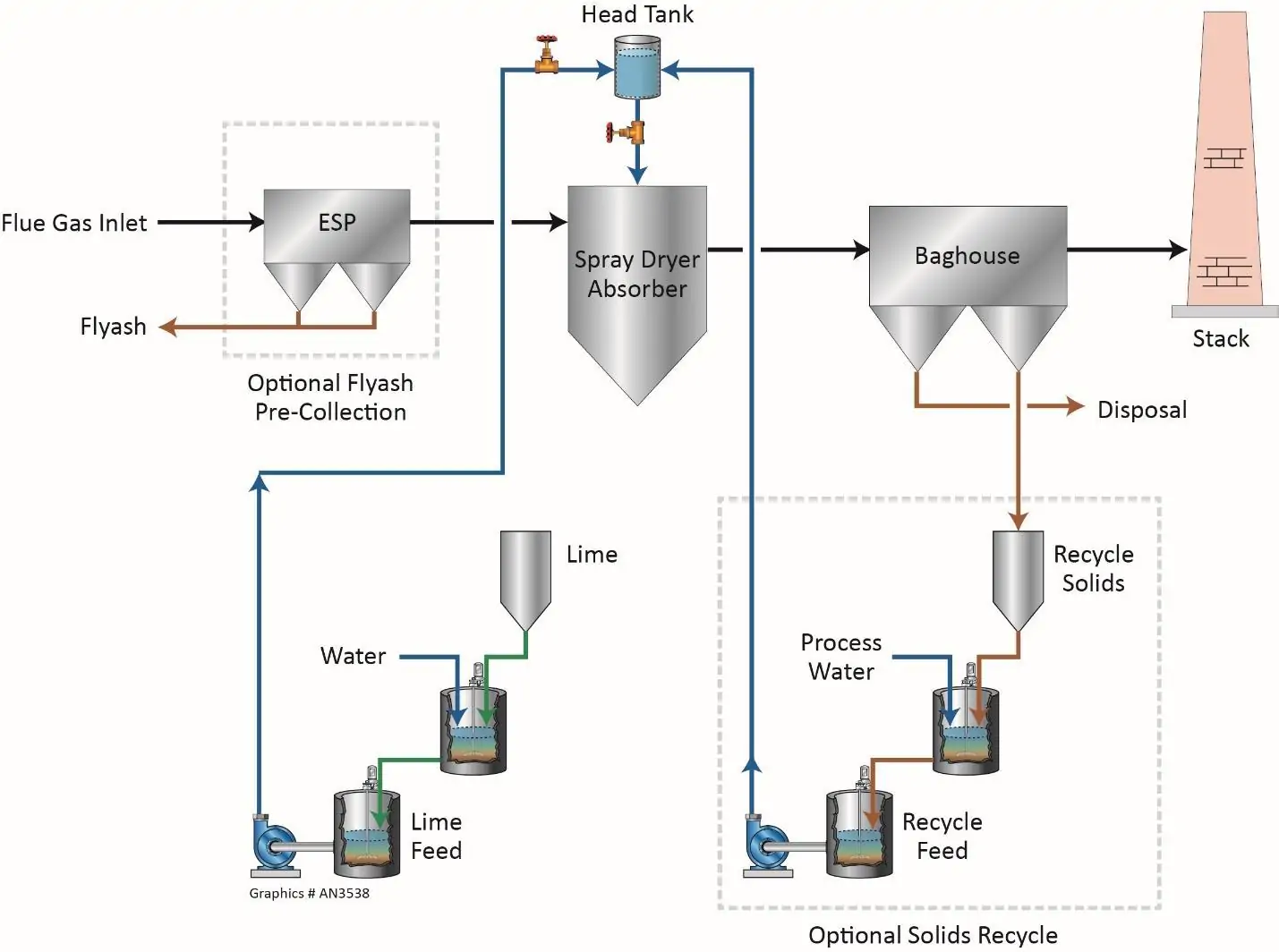
Figure 5.1.12a Basic schematic of a spray-dryer scrubber.
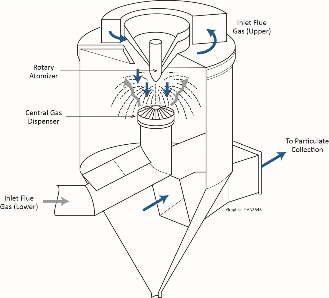
Figure 5.1.12b Cutaway view of a common spray nozzle assembly.
The key components include the lime slaker, the absorber with atomizers that convert the lime slurry into uniformly spread small droplets at the emission point, and the particulate collector, typically a fabric filter device. Providing droplets that have enough moisture to absorb SO2 from the flue gas and complete the required reaction with lime, but that also will dry in the heat of the flue gas such that completely dry solid particles arrive at the particulate collector is vital to this process.
The ability to incorporate mercury removal methods into the dry scrubbing process has been an attractive feature for some plants. Additional details on this technology are outlined in the next section.
In addition to air emissions discharge, harmful impurities can also exit coal plants in a variety of aqueous pathways, as the figure below illustrates.
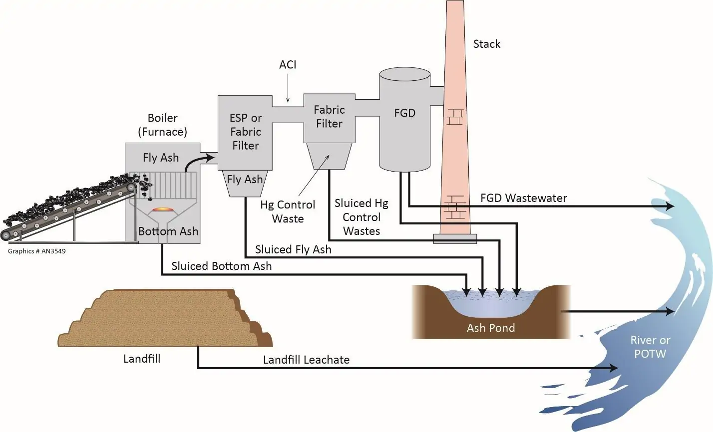
Figure 5.1.13 Basic schematic of the paths available for power plant emissions, and accompanying impurities, to reach the environment.
The initial reaction product in a wet-limestone or lime scrubber is calcium sulfite hemihydrate, as shown in Equation 9. This material has no real value and is difficult to dewater for disposal. Accordingly, most wet-limestone or lime scrubbers were equipped with forced-air oxidation systems to produce a gypsum byproduct, as previously shown in Equation 11. In many cases, the byproduct has been of sufficient quality for use by the wallboard industry or other applications, though landfilling was the only disposal method on some occasions. Although dried gypsum typically contains no more than 15% moisture, subsequent exposure to atmospheric precipitation increases the potential for transport of leachate to the environment.
A substantial volume of FGD wastewater is produced by scrubber bleed, much of it from the dewatering of the gypsum byproduct. These streams contain significant concentrations of dissolved ions, including calcium, magnesium, chloride, sulfate, and trace metals, potentially including mercury and selenium. Removing these constituents from plant discharge has often been the toughest challenge of wet scrubbing. Hardness removal can be achieved through lime-softening clarification; however, other impurities are more challenging to eliminate. For example, almost all chloride salts are very soluble, making it is nearly impossible to remove chloride by precipitation reactions. A complex and expensive method for chloride removal, utilized at some plants in arid locations, involves evaporation and crystallization. Such systems consume excessive amounts of energy and require exotic, corrosion-resistant materials in portions the process.
Compounding these issues are concerns related to potential discharge of toxic trace metals or metalloids.
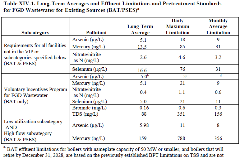
Discharge of trace impurities from wet scrubbers and ash ponds at operating and shutdown facilities is a prominent concern. Many ponds are being closed to prevent further contamination of surface water and groundwater from these impoundments. The table below outlines the four priority parameters, selenium, arsenic, mercury, and nitrate/nitrite, which are to be placed in the EPA “Effluent Limitations Guidelines” for WFGD wastewaters.
Table 5.1.1 (Source: Environmental Protection Agency Guidelines)
Selenium typically exists in two oxidized states in FGD wastewater: selenite (SeO3) and selenate (SeO4). The latter tends to predominate in forced-air oxidized systems. The EPA’s best available technology (BAT) for selenium removal has been biological treatment with adsorption of the oxidized selenium compounds on an organic substrate, with subsequent digestion of the selenium oxides by microorganisms that convert the compounds to elemental selenium retained by the microbes. These systems are very large and expensive, and they require periodic removal of spent organisms and replenishment of the microbiological substrates.
Beyond issues related to FGD wastewaters, trace metals and metalloids in ash ponds at both operating and closed plants are an additional concern. In several well-publicized incidents, large quantities of ash and water were accidentally released into the environment, which has drawn increased attention to this issue. Apart from these incidents, however, pond remediation does not allow for the water to be directly drained to a receiving body of water such as a river or lake. Rigorous treatment[i] may be necessary before ponds can be drained and closed.
ChemTreat’s patented physical-chemical process for selenium removal[j] utilizes traditional water treatment equipment like clarification, which was formerly ineffective because of interference by competing ions. (See US Patent No.11,066,313 B1, Methods for removing anions from water.) Modern advancements in chemistry have enabled precipitation reactions that ensure the sequestration of selenium in solid waste forms, allowing for their secure landfill disposal. Data from Toxicity Characteristic Leaching Procedure (TCLP) trials thus far have indicated that the solids generated from these processes exhibit significant stability.
Mercury generation during coal combustion and the methodologies for its mitigation represent a complex process, with primary issues originating at the combustion stage. Though coals contain minute amounts of mercury, it’s high toxicity results in air emissions regulations calling for an extremely low quantity in flue gas discharge. The MATS regulations, placed into effect in 2011, essentially called for a 90% reduction of mercury from power plant stack emissions. Despite efforts by the Trump administration to relax regulations, the majority of plants had already adopted measures to mitigate mercury emissions.
Natural or artificial oxidation of the element is key to mercury removal from flue gas. Many bituminous coals contain a relatively significant amount of chlorine, which, when released during combustion, will oxidize mercury from its elemental state (Hg0) to an oxidized state (Hg2+). Oxidized mercury escapes flue gas in scrubbers. Sub-bituminous coals, such as those from the Powder River Basin, contain much less chlorine. Thus, most of the mercury remains in elemental form. As elemental mercury is not absorbed by scrubber reagents, it passes through the scrubbing solution. Spray of a salt solution, often sodium bromide, on coal at a spot on the conveyor system, or injection of bromide-containing activated carbon in the flue gas of systems with dry scrubbers are common techniques utilized to oxidize mercury.
One consequence of capturing mercury by wet scrubbing is that the element is merely transferred from its gaseous state to a liquid phase, without being rendered environmentally harmless. However, chemistry has been developed that can be utilized in wastewater treatment systems to capture mercury and bind it tightly with the byproduct solids. This chemistry, in addition to methods that capture arsenic and remove nitrates, has been incorporated into the selenium removal technology outlined above. Together, these offer a complete process for handling the impurities shown in Table 5.1.1.
With the reduction of coal-fired power driven by environmental and economic factors, the primary alternatives became renewable energy and natural gas-fired generation, particularly in simple and combined cycle configurations. Simple cycle units rely on a combustion turbine (similar to aircraft engines) for primary power (the Brayton cycle), with combined cycle featuring one or more heat recovery steam generators (HRSGs). HRSGs utilize exhaust heat from the combustion turbine(s) to generate steam that powers steam turbines (the Rankine cycle). Modern combined cycle units may operate at net efficiencies of 60% or slightly higher, which is significantly greater than the most efficient coal-fired unit. These high efficiencies led to a preponderance of combined cycle plant installation in the first two decades of this century.
Natural gas is a very clean fuel, thereby eliminating the ash-related challenges and numerous emissions issues associated with coal-fired boilers. However, NOx and carbon monoxide are two primary pollutants that still must be addressed with combustion turbine technology. Unlike coal combustion, virtually all NOx produced from combustion turbines is thermal NOx, in which the high temperatures in the turbine combustors induce a reaction between the elemental oxygen and nitrogen in the compressed air feed. For simple cycle units, the injection of a small stream of high-purity water or steam to slightly lower combustion temperatures is a common method. Combined cycle units often utilize SCR, similar to the design outlined above, for NOx control, with ammonia as the reactant. Although natural gas does not contain the catalyst poisons commonly present in coal, catalyst degradation will still occur. Two potential sources of poisons include sodium and phosphorus. “The former may enter the gas stream from (1) water injected into the engine for NOx control or power boost, (2) off-spec water used in the production of aqueous ammonia, and (3) ambient sources for units located near the coastline. Phosphorus comes from lube oil that finds its way into the [gas turbine] GT exhaust stream.”3
Inclusion of a catalyst bed to oxidize residual CO to CO2 is also common for HRSGs. The placement of the CO and NOx catalyst beds within HRSG evaporator and superheater/reheater bundles can be variable depending upon the ideal temperature range of the catalyst.
Appendix 5-2
Power and industrial coal-fired boilers are among the most heavily regulated sources of air emissions because of their significant production of air pollutants. However, other industrial processes also produce gaseous emissions that necessitate treatment, often allowing the gas to be repurposed within the facility or converted into a useful product. One must always consider that the process of removing pollutants from flue gas or other emissions converts these substances into either liquid or solid forms. Though many of these byproducts are less hazardous than the original pollutant, they must still be handled or disposed of carefully.
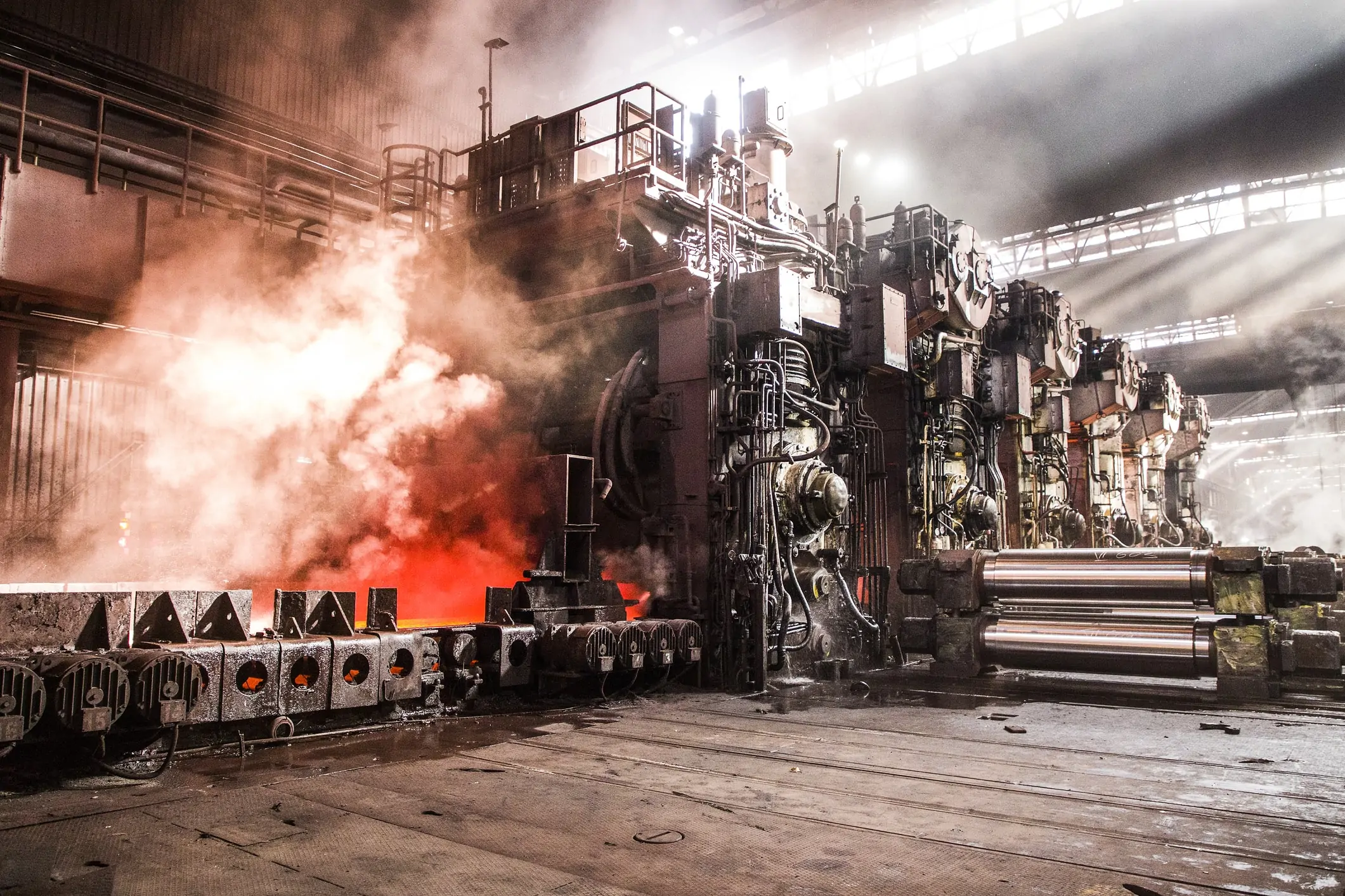
Appendix 5-1 provides an overview of particulate removal methods specific to the power industry, though similar methods may be applicable at other facilities. One notable example is particulate control from steel mill furnaces. Consider blast furnace operation, for example. Although the number of blast furnaces has declined precipitously over the years, they are still the heart of integrated mills. To produce a batch of molten steel for further refinement during each “heat”, the furnace charge includes coke and limestone to remove oxygen from the iron ore and collect impurities as a slag that can be drained. The gaseous exhaust from the top of the furnace contains carbon monoxide (CO) and carbon dioxide (CO2). As carbon monoxide is not fully oxidized, the off-gas serves as a valuable fuel for low-pressure steam generators in the plant. However, the gas must be cleaned of particulates before further use. In general, these particulates consist of limestone, coke, and iron ore fines. Electrostatic precipitation (ESP) is common to remove the bulk of the particulates. Wet scrubbing often follows the ESP to remove residual particles. The waste stream from the wet scrubber must undergo processing by clarifiers and filters to eliminate remaining particles and impurities, including organic compounds like phenols that may be present.
Blast furnaces produce pig iron, which must be refined into higher grades of steel. This process is typically performed in basic oxygen furnaces (BOF). Additionally, a number of facilities have emerged that produce steel from scrap metal in electric arc furnaces (EAF). The exhaust from BOF and EAF furnaces also contains particulates. Wet scrubbing, which also cools the furnace exhaust gas, is common in these applications.
Many industrial processes produce acid gases. Examples include metal pickling, direct acid production, and municipal waste combustion. The most common acids from these processes include hydrochloric (HCl), sulfuric (H2SO4), and hydrofluoric (HF). Several methods are available to remove the acids. One technique is spray dryer scrubbing to contact the gas with a fine spray of lime slurry that converts the acids to calcium salts that can then be collected in a fabric filter system. A spray-dryer scrubber configuration is illustrated in Appendix 5-1.
Some unit processes in the refinery industry generate complex gas streams. Hydrotreating, in particular, is performed on numerous effluent streams from atmospheric and vacuum distillation towers to eliminate nitrogen and especially sulfur, which could contaminate catalyst beds in subsequent cracking and reforming units. Elemental hydrogen is blended with the system feed, which is then heated and conveyed to the reaction vessel. Hydrotreating produces ammonia (NH3) and hydrogen sulfide (H2S), a highly toxic compound. However, H2S can be converted to useful products, as outlined in this appendix.
Hydrotreater exhaust gas is typically scrubbed with an amine solution.
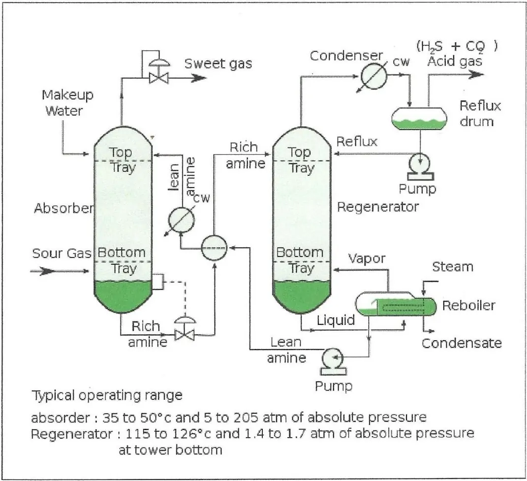
AmineTreating by Raminagrobis is licensed under CC BY-SA 4.0
Figure 5.2.1 Basic flow diagram of H2S (and CO2) removal by amine scrubbing.
Lean amine supplemented with makeup water enters the top of the reactor vessel (on the left side of the diagram) and removes the acid gas. The rich amine solution is then introduced to the regenerator to release H2S and CO2 and recover the amine for reuse.
Some of the amines that have been employed for this process include:
The Claus process, recognized for its effectiveness in producing elemental sulfur, converts hydrogen sulfide emitted from the “regenerator” into a non-toxic product. The H2S stream is combusted with a lean stream of air to convert 1/3 of the hydrogen sulfide to sulfur dioxide (SO2). This compound then partially reacts with the remaining H2S as follows:
|
2H2S + SO2 → 2S + 2H2O |
The hot gas is routed through a condenser, where potentially up to 70% of the initial sulfur is extracted as elemental sulfur. However, substantial amounts of H2S remain, and the gas is typically fed through two or three reheater/catalyst vessel units that convert most of the remaining H2S to elemental sulfur. The sulfur can then be shipped to facilities for conversion into sulfuric acid, which is the largest commodity chemical in the country.
The West Gas Sulfuric Acid (WSA) technology, develop by Haldor Topsoe, is an alternative to the Claus process. In this process, the H2S is completely combusted to SO2, which is then catalytically oxidized to sulfur trioxide (SO3) and converted into H2SO4. This is a more direct method for producing sulfuric acid than the Claus process.
Amine chemistry also removes carbon dioxide from waste gas or boiler flue gas. This method has been touted as a solution for continued use of coal as a fuel for power boilers. The overall technology is known as carbon capture and sequestration (CCS), where up to 90% of the CO2 is converted to a concentrated stream and injected underground for sequestration. In some applications, the CO2 is pumped into depleted oil fields to force hard-to-recover petroleum to the surface in a process known as enhanced oil recovery (EOR). Further research into development of amines or other compounds that readily capture CO2 but minimize heat requirements for regeneration is ongoing. Combined with EOR, CCS may offer an economic incentive to continue some coal-fired power generation.
Cement production is another industry that generates vast quantities of CO2. Approximately 2/3 of a Portland Cement mixture consists of calcium oxide (CaO), which is generated from the decomposition of calcium carbonate in kilns.
|
CaCO3 + heat → CaO + CO2↑ |
Several methods are currently being researched to reduce CO2 emissions from cement plants, including techniques to incorporate CO2 in concrete mixtures, partial replacement of lime with coal boiler ash and blast furnace slag, and the potential use of the afore-mentioned CCS technology.
The byproduct fine powders from various industrial processes create a substantial fire and explosion hazard at many facilities. Further, the inhalation of these fine particles by plant workers can present an additional health hazard. Examples of materials that can exist as fine particulates or be converted into fine particles for process use include:
Dust control is crucial at facilities where particulates are generated. A well-designed plant-wide cleaning system can be essential in preventing dust accumulation. A vacuum system that pulls airborne particulates into a central filtering device is common component of these systems. This central filtering device could be a fabric filter, or baghouse, comparable to those previously mentioned in this chapter, but operating at ambient conditions. Cartridge dust collectors offer an alternative for smaller applications. Cyclone dust collectors are also common at some facilities, either stand-alone or as pre-filters ahead of a baghouse.
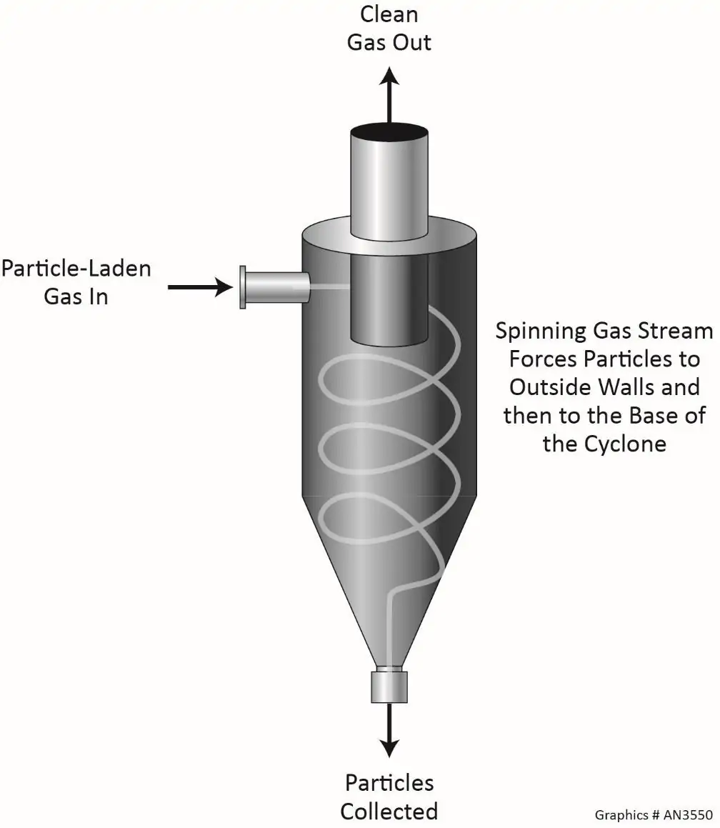
Figure 5.2.2 Cyclone dust collector.
These are often utilized for coal-unloading and transport facilities at power plants. Wet scrubbing may be the best option for difficult or hazardous particles.
In conclusion, the indoor environment in many plants can be hazardous. While it is common to focus on treatment of the gases emitted by unit processes, maintaining sufficient ambient air quality is vital as well.

President of Buecker & Associates, LLC
Brad Buecker is President of Buecker & Associates, LLC and most recently served as Senior Technical Publicist with ChemTreat. He has over four decades of experience in or supporting the power industry, much of it in steam generation chemistry, water treatment, and air quality control. Buecker has a B.S. in Chemistry from Iowa State University. He has authored or co-authored over 250 articles for various technical trade magazines and has written three books on power plant chemistry and air pollution control. He serves on the Editorial Advisory Board of Water Technology and is a member of the ACS, AIChE, AIST, ASME, NACE (now AMPP), and the Electric Utility Chemistry Workshop planning committee.
The ChemTreat Water Essentials Handbook would not have been possible without the contributions of many people. See the full list of contributors.