-
USA - English
- Locations
- SDS Access
- CTVista®+ Login

By Brad Buecker and Prasad Kalakodimi, PhD
This article was originally published in PPCHEM® Journal; PPCHEM® 2021, 23(5), 198–205; https://journal.ppchem.com/
Heat exchangers are, of course, a critical component of power and heavy industrial plants. Many of these are water cooled, with the source being a cooling tower (commonly known as an open cooling system) or sometimes once-through cooling. Often, "closed" systems are also present, which are cooled by primary heat exchangers, but whose chemistry is significantly different from that of open systems. Successful chemical treatment of the wide variety of cooling systems in plants requires analysis of many factors, including the potential for corrosion, scaling, and microbiological fouling, system metallurgy, operating temperatures, and others, all of which are examined in this article. Also discussed are several significant improvements to chemical treatment programs in recent years, improvements that maintain proper heat transfer and reliability of cooling systems.
At steam generating power plants, the primary water-cooled heat exchanger is the steam surface condenser, unless, of course, the plant has an air-cooled condenser (ACC). Several other heat exchangers are also present, including the turbine lube oil cooler, bearing cooling water heat exchanger, and the hydrogen cooler. Many additional heat exchangers are utilized at large industrial plants such as refineries, petrochemical plants, etc. A wide range of designs is possible: from shell-and-tube to plate-and-frame to jacketed systems and others. Cooling systems may be open or closed. These complex arrangements usually require a variety of treatment methods. Furthermore, unlike in modern power plants, where materials selection has gravitated towards all-ferrous metallurgy throughout the condensate, feedwater/economizer, and boilers, several metals may be present in industrial systems. Copper alloys are quite common as the tube material in shell-and-tube heat exchangers.
Many factors can influence cooling system and heat exchanger performance and reliability, with a general representation outlined in Figure 1.
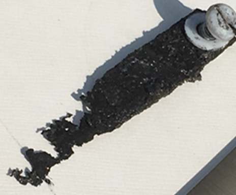
Figure 1. The corrosion-deposition-biofouling triangle.
As this diagram suggests, corrosion, scale formation, and biological fouling are not individually exclusive. A plant’s chemical treatment program needs to account for all three factors, and indeed the triangle could even be expanded to include environmental issues [1]. In the first portion of this article, we will focus on open systems, and primarily those supplied from cooling towers.
A classic example of concurrent issues can be seen in Figure 2, which shows a multi-pass tube-and-shell heat exchanger, whose cooling water at the time was treated with a traditional phosphate-based program.
Figure 2. Multi-pass heat exchanger on a phosphate program just prior to a change in treatment chemistry.
At the inlet end of the heat exchanger (the tubes on the bottom of this unit), corrosion was problematic. At the warmer outlet side (on the top), deposition and scale formation was occurring. Thus, the program was not particularly effective at mitigating corrosion or deposition depending on location. We will return to this example later in the article.
From a microbiological perspective, cooling systems provide an ideal environment, warm and wet, for microbes to proliferate and form colonies. Bacteria can grow in heat exchangers and cooling tower fill, fungi on and in cooling tower wood, and algae on wetted cooling tower components exposed to sunlight. A major problem with microbes, particularly some bacteria, is that once they settle on surfaces, the organisms secrete a polysaccharide layer (slime) for protection. This film can severely inhibit heat transfer, and it can also collect silt from the water and grow thicker, further degrading heat exchange (see Figure 3). Biofilms restrict heat transfer more effectively than almost any other deposit. Furthermore, heavy fouling can drastically reduce fluid flow, sometimes to the point of complete blockage.
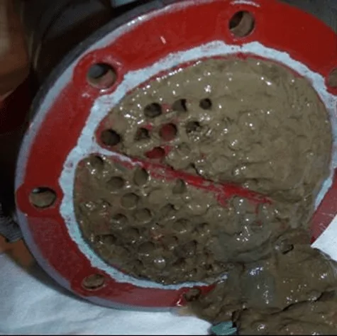
Figure 3. Heat exchanger tubes fouled with microbes and slime.
In another nod to Figure 1, the protective slime layer formed by initial bacterial deposits allows anaerobic and facultative bacteria underneath to flourish. These organisms can generate acids and other harmful compounds that directly attack metals. Microbial deposits also establish concentration cells, where the lack of oxygen underneath the deposit causes these locations to become anodic to other areas of exposed metal. Metal loss occurs at the anodes, with pitting as the result (see Figure 4).
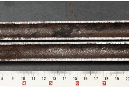
Figure 4. A large under-deposit corrosion pit (with deposit removed) in a stainless steel heat exchanger tube.
Of course, proper chemistry control to minimize fouling and scaling is a key method to help maintain heat exchanger reliability and performance, as we will explore later, but a benefit of the shell-and-tube design over others is the ability, in many cases, to remove slimy deposits and some hardness compounds by mechanical cleaning. Mechanical cleaning of other heat exchangers, for example plate-and-frame units (Figures 5a b), can be much more difficult, if not impossible.
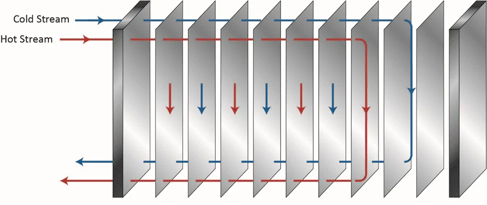
Figure 5a. Basic flow diagram of a single-pass plate-and-frame heat exchanger.
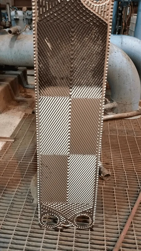
Figure 5b. An individual plate from a plate-and-frame heat exchanger. Lower part of the plate already cleaned by water jet washing, upper part uncleaned, exhibiting fouling that reduced heat transfer.
The narrow spacing between the plates offers a prime setup for fouling and deposition, and as Figure 5b illustrates, the plates are often designed with a corrugated or similar pattern to enhance fluid turbulence and heat transfer. Even so, fouling and deposition cannot be hindered completely.
Another very important aspect of corrosion/deposition issues in heat exchangers is the wall surface, also known as the skin, temperature. While the general increase in bulk cooling water temperature as the water passes through a heat exchanger can influence many reactions, additional or more pronounced reactions are possible at the metal surface, where temperatures may be significantly higher than in the bulk water. This is a factor to consider when evaluating heat exchanger design, metallurgy, and chemical treatment programs.
Cooling towers are another set of heat exchangers susceptible to corrosion, scaling, and especially fouling. Figure 6a shows cooling tower fill with heavy fouling. In Figure 6b, long algae threads hang from the fill to nearly the cooling tower basin.
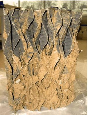
Figure 6a. Fouled cooling tower film fill.
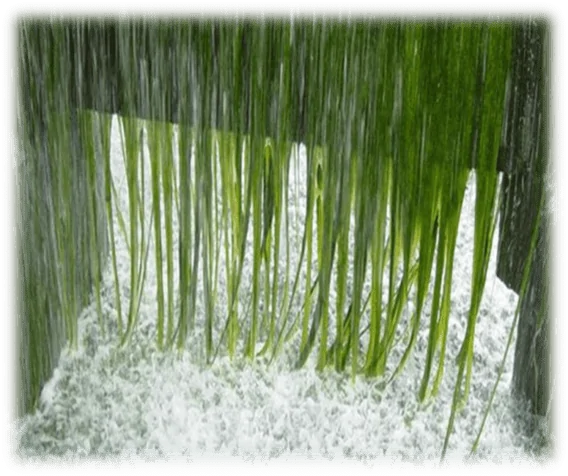
Figure 6b. Severe algae growth in a cooling tower.
Treatment methods for controlling the “big three” issues of the Figure 1 triangle have been addressed by the authors in a previous article for this journal [2]. To recap: During the middle of the last century, chromate (CrO42-) coupled with sulfuric acid feed was very popular for corrosion and scale control in many cooling systems. While chromate is considered an anodic inhibitor, with sufficient dosage, it will form a complete surface layer of iron chromate (pseudo-stainless steel), which can be quite protective. Acid feed to maintain a cooling water pH within a 6.5–7.0 range converts much of the bicarbonate ion (HCO3-) alkalinity to CO2, which escapes as a gas. Reduction of alkalinity greatly reduces the potential for calcium carbonate (CaCO3) scaling, which is typically the first mineral deposit that would otherwise precipitate without treatment. Chromate/acid chemistry is very straightforward and effective; however, environmental issues related to chromium discharge, particularly with respect to the toxicity of hexavalent chromium (Cr6+), led to abandonment of this method.
Treatment then evolved to phosphate-based chemistry for both scale and corrosion prevention. These programs typically function at a mildly alkaline pH range of approximately 8.0–8.5, which minimizes general corrosion. The chemistry also provides additional corrosion protection, as phosphate will react with ferrous ions (Fe2+) produced at anodic sites to form a reaction-limiting deposit, while calcium phosphate (Ca3(PO4)2) precipitates in the local alkaline environment at cathodic sites to inhibit electron transfer. However, even small upsets in phosphate programs can cause severe calcium phosphate fouling, and at one time, Ca3(PO4)2 deposition became almost as great a problem as calcium carbonate scaling had been before. Treatment methods evolved to more forgiving methodologies, with organic phosphate (also known as phosphonate) as the backbone in many cases, supplemented with polymer for calcium phosphate deposition control. Phosphonates attach to deposits as they are forming and disrupt crystal growth and lattice strength.
Even with these improvements, many problematic issues remain with phosphate/phosphonate treatment, including increasing concern about phosphorus discharge to the environment. These issues have led to advanced methodologies with the core functionality based on reactive polyhydroxy starch inhibitor (RPSI) chemistry as exemplified by, for example, ChemTreat’s FlexPro® technology. By virtue of many active sites on the molecules, these compounds attach to the base metal and form a protective layer. Common RPSI formulations also include advanced polymers that inhibit scale formation by crystal modification and ion sequestration. Figure 7 shows the same heat exchanger from Figure 2 following cleaning and changeover to FlexPro® treatment.
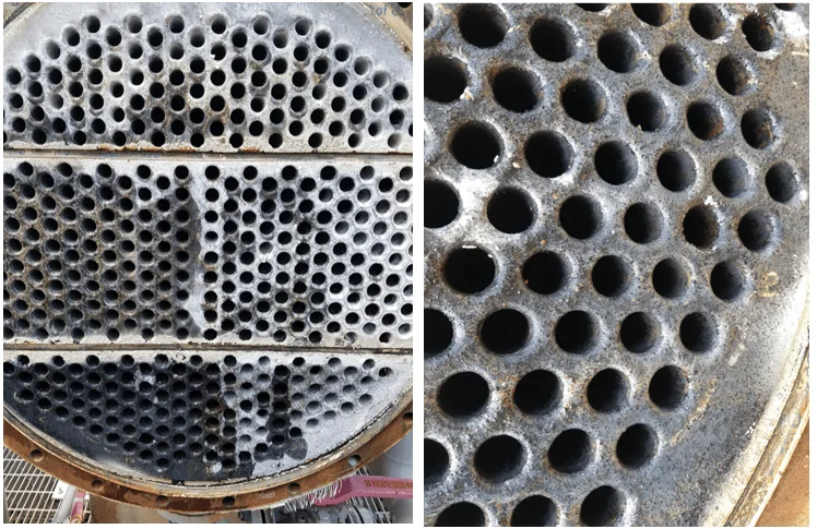
Figure 7. The heat exchanger from Figure 2 on FlexPro® chemistry. Tubes are essentially free of corrosion and deposition.
Most modern cooling tower chemical treatment programs operate in a mildly basic pH range of 8.0–8.5. Chlorine gas was the workhorse for microbiological treatment for many years, although liquid bleach (NaOCl) feed supplanted gaseous chlorine at many plants for safety reasons. When chlorine is added to water, the following reaction (Eq. (1)) occurs:
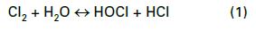
Hypochlorous acid (HOCl) is the killing agent, and it functions by penetrating cell walls and oxidizing internal cell components. The efficacy and killing power of this compound are greatly affected by pH because of the equilibrium nature of HOCl in water, as shown in Eq. (2).

OCl- is a much weaker biocide than HOCl, probably because the charge on the OCl- ion does not allow it to effectively penetrate cell walls. The dissociation of hypochlorous acid dramatically increases as the pH rises above 7.5. Because many cooling tower scale/corrosion treatment programs operate at an alkaline pH, chlorine chemistry may not be the best choice for some applications. Chlorine efficiency is further influenced by ammonia and organics in the water, which react irreversibly with the chemical and increase chlorine demand.
A popular solution to this difficulty has been bromine chemistry, where a chlorine oxidizer (bleach is the common choice) and sodium bromide (NaBr) are blended in a makeup water stream and injected into the cooling water. This chemistry produces hypobromous acid (HOBr), which has similar killing powers to HOCl but functions more effectively at an alkaline pH. Figure 8 compares the dissociation of HOCl and HOBr as a function of pH.
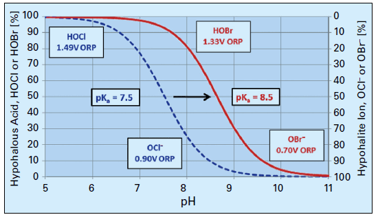
Figure 8. Dissociation of HOCl and HOBr vs. pH.
Many facilities such as refineries, chemical plants, steel and paper mills, food and beverage plants, etc., often have cooling systems with waters containing elevated organics, nitrogen species, or other impurities that severely inhibit the performance of conventional oxidizers. Accordingly, ChemTreat researchers have improved upon and developed alternative oxidizing biocides that may perform much more effectively in difficult cooling waters. One is monochloramine (NH2Cl) with precise generation for each application. This compound is a weaker oxidizer than chlorine or bromine, but research and operating experience show the chemical to be more effective than chlorine or bromine at penetrating the protective bacterial slime layer that consumes stronger oxidants.
Another option is a specialty solution of chlorine dioxide (ClO2). This compound is a selective oxidizer, but even though it is chlorine-based, it does not react with ammonia and reacts less vigorously with some organics than chlorine. Furthermore, the compound is not influenced by pH. On-site chlorine dioxide generation is required, as large quantities of chlorine dioxide cannot be safely stored in containers or tanks. However, most modern production methods include more safeguards and safety checks than past technologies.
For those plant personnel who still wish to use bleach (sodium hypochlorite), but whose cooling systems face at least some of the challenges mentioned above, the use of halogen stabilizers may be a good choice. These products typically contain a combination of halogen stabilizer and bio-penetrant. The former, as its name implies, stabilizes the chlorine in solution and provides a controlled release. The bio-penetrant aids biocide efficacy by destabilizing protective slime layers to allow the oxidizer better access to the underlying organisms.
At some plants, oxidizer feed is limited to two hours per day, which gives microbes time to settle and form colonies during off times. Accordingly, a supplemental feed of nonoxidizing biocide on perhaps a once-per-week basis can be quite effective in controlling biological growth. Nonoxidizers in conjunction with bio-penetrants reduce overall chlorine usage and do not produce halogenated organic byproducts. Table 1 below lists properties of some of the most common nonoxidizers.
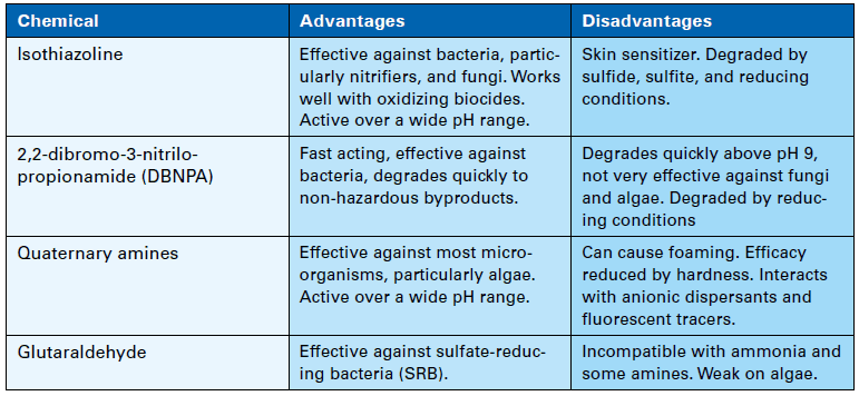
Table 1. Nonoxidizing biocides.
Careful evaluation of the microbial species in the cooling water is necessary to determine the most effective biocides. Antimicrobial compounds should not be used or even tested without approval from the appropriate regulating agency. They must be incorporated into the plant’s discharge permit. Also, as with all chemicals, safety is an absolutely critical issue with biocides. Safety Data Sheet (SDS) guidelines should be followed to the letter when handling these products.
Many plants have numerous heat exchangers that are usually embedded in a closed cooling water system, which rejects heat to the primary open recirculation cooling system (see Figure 9).
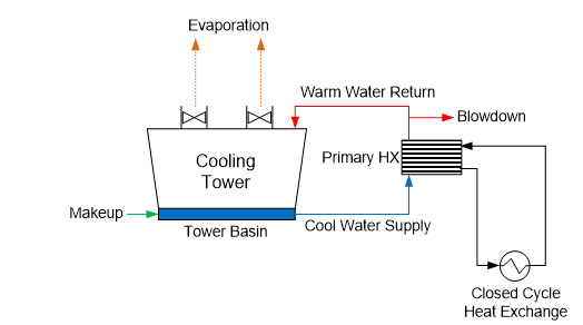
Figure 9. General schematic of a primary open-recirculating and secondary closed cooling system arrangement.
The term “closed” cooling water system is somewhat of a misnomer, as virtually all systems have leaks or small losses somewhere that require makeup. (If serious corrosion has occurred, these losses may be significant.) Systems are often designed with a head tank for water makeup and handling changes in demand. This arrangement can allow some oxygen to enter the cooling water, which, of course, influences the corrosion potential.
While it may be possible to utilize water with varying qualities in CCW systems, a common choice, and our main focus here, is specially-treated condensate or demineralized water. Choosing condensate over less pure water minimizes the possibility of difficulties from scale-forming hardness compounds or corrosive agents such as chloride and sulfate.
A typical piping material for CCW systems is carbon steel, with stainless steel or perhaps copper alloys being a common choice for heat exchanger tubes or plates in plate-and-frame exchangers. Other metals may include aluminum or those metals contained in the solder of fittings within heat exchanger cooling coils. When planning a treatment program, it is important to know the entire system metallurgy.
Corrosion inhibitors slow reactions at either the anode, the cathode, or sometimes both sites of electrochemical cells. A very common treatment method, based on cost and ability to protect carbon steel, is nitrite applied via injection of sodium nitrite (NaNO2) to the cooling circuit. When carbon steel is first placed into service, the metal surface develops an oxide layer. While formation of this oxide coating is a corrosion mechanism, the layer serves as a protective film for the base metal underneath. However, the natural oxide layer can be damaged by mechanical influences or penetrated by corrosive agents. Nitrite forms a passivating iron oxide film at anodes that can eventually cover the entire steel surface. A representative reaction of this chemistry is outlined in Eq. (3).

An important aspect to be noted from this equation is that the nitrite reaction produces ammonia, which can induce corrosion of copper alloys, particularly if an oxidizing element or compound such as oxygen is also present in the water. The pH of these solutions is typically adjusted to a range of 8.5–11 with an alkaline compound such as sodium hydroxide or the buffering agent sodium tetraborate, commonly known as borax.
A key concept with regard to anodic inhibitors such as nitrite is that the chemical concentration should not be allowed to fall below a minimum value. If the level drops too low, anodes will develop in what is otherwise a large cathodic environment, establishing localized sites for very intense corrosion. Through-wall pitting may be the result. A common range for nitrite concentration is 500–1,500 mg∙L-1. The authors have worked with closed cooling systems in which this range could not be maintained because of significant leaks. Treatment was suspended to protect the remainder of the piping from localized corrosion. The proper response to such issues is repairing and replacing corroded piping to return the system to “closed” status. Plant management may not always agree with this philosophy because of the cost and complexity of the task. However, large leakage requires large makeup. Excessive feed of oxygen-saturated makeup propagates corrosion.
One disadvantage of nitrite treatment is that the chemical serves as a nutrient for certain bacteria, such as Nitrobactera Agillis, which converts nitrite into nitrate (NO3-), which, in turn, can generate significant slime. Author Brad Buecker once observed a nitrite-treated closed cooling water system at a large automobile assembly plant, in which microbial slime restricted flow in the small-bore cooling coils of automated welding devices. Overheating became a problem. Also, some microorganisms, via their metabolic processes, produce acids and other harmful byproducts that can directly attack metals via the mechanism known as microbiologically-induced corrosion (MIC).
Another corrosion inhibitor option, albeit a more expensive one, is molybdate (MoO42-), which is generated by the addition of sodium molybdate (Na2MoO4) to the cooling water. Like chromate, molybdate binds with iron to form a surface layer of ferrous molybdate (FeMoO4). This compound provides good protection, particularly against the harmful anions chloride and sulfate. A common dosage range is 200–1000 mg∙L-1, with a typical recommended pH range of 9.0–11.0. Nitrite and chromate can be blended to provide a synergistic effect, where the nitrite enhances tighter molybdate bonding. Often in these cases, the control range for each chemical is slightly lower than if utilized individually.
Other protection methods are available, including protection by silicates, and the use of a reducing agent such as hydrazine to maintain the passive Fe3O4 (magnetite) layer on carbon steel and cuprous oxide (Cu2O) on copper alloys. However, for copper alloys, azole chemistry is often the best choice. A common member of the azole group is tolyltriazole (TTA), whose structure is shown in Figure 10.
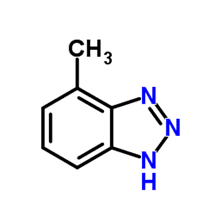
Figure 10. Basic structure of TTA.
When utilized in basic solutions, which is common for nitrite and molybdate, the molecule deprotonates (loses the hydrogen ion), and nitrogen bonds to the copper surface. The organic rings of the compound form a plate-like film to protect the base metal.
In a closed system with no organic loading, the conditions are theoretically unfavorable for microbiological fouling. Yet, as has already been noted, fouling can be problematic in some systems, and particularly those that use some form of organic chemicals, e.g., azoles or dispersants, which can break down and provide food for microbes. Add a nutrient such as nitrite, or its reaction product, nitrate, and significant problems may arise. If the system utilizes water other than condensate, other microbes such as sulfate-reducing bacteria may proliferate.
Therefore, microbiological treatment may be necessary, but unlike open cooling systems, oxidizing biocides are typically not utilized in closed systems. Oxidizers can react with some corrosion inhibitors such as nitrite or introduce corrosive species, e.g., chloride, to the water. Nonoxidizing biocide