Introduction to Industrial Wastewater Treatment Methods
The variety of chemicals and materials produced at industrial plants around the globe create various wastewater treatment issues. Waste streams may contain any number of problematic and/or toxic compounds that must be removed before discharge. Some of the potential treatment methods are similar to those we examined for makeup water treatment, e.g., clarification/media filtration, while other technologies have recently emerged as replacements for older, less efficient methods.
Some wastewater streams such as cooling tower blowdown may be discharged directly to a receiving body of water provided the discharge meets fundamental environmental regulations. Conversely, the physical properties and chemistry of the receiving water source can greatly influence discharge requirements, which may in turn require a high level of treatment in an on-site wastewater plant. This chapter examines emerging wastewater issues and outlines modern techniques for industrial wastewater treatment.
This section briefly reviews key impurities that may be present in wastewater streams. The discussion serves as a precursor for the following examination of treatment techniques.
When discharge guidelines first began to emerge with the passage of the Clean Water Act (1972) and development of National Pollutant Discharge Elimination System (NPDES) regulations, one of the first regulatory targets was once-through power plant cooling water effluent. The four primary parameters were suspended solids, oil and grease, pH, and residual oxidizing biocide. Many other contaminants have entered regulatory consideration since, and this data may be found in Reference 1. The next sections provide a general overview of wastewater impurities as a foundation for treatment method discussion.
Particulate matter entrained in water is known as suspended solids; the analytical reporting term is total suspended solids (TSS). Suspended solids control is important to minimize sludge buildups at the plant discharge, and to prevent entrained toxic materials from being discharged with the solids. TSS may be a reporting requirement and it is a method to evaluate the performance of chemical coagulation/flocculation systems, filtration systems, and activated sludge treatment systems.
Oil and grease refer to the fats, oils, waxes, and other related materials found in wastewater. Oil and grease (O&G) analysis identifies these foulants that may be present in the wastewater discharge. Oil and grease reduction is often required upstream of biological wastewater treatment systems, as excessive O&G can foul equipment and lower the oxygen uptake efficiency of activated sludge microorganisms.
Later sections in this chapter discuss the techniques of oil skimming and dissolved air flotation (DAF) for O&G removal.
Many wastewater streams contain either acidic or alkaline (basic) compounds. These can seriously harm aquatic organisms. A common NPDES discharge pH range is 6.0–9.0. (Some local or regional guidelines may have a slightly different range.)
Chapter 7 provided details on both oxidizing and non-oxidizing biocide feed for control of cooling system microbiological fouling. Reduction of residual biocide concentrations at the plant discharge may be necessary for some wastewater systems.
At refineries, petrochemical plants, and related facilities, organic chemicals often appear in wastewater streams. These compounds may range from small molecules to large chains, and some may be directly toxic to aquatic creatures, animals, and humans. Additionally, organics and O&G (and nutrients such as nitrogen and phosphorus) directly influence the biochemical oxygen demand (BOD) and the chemical oxygen demand (COD) of receiving waters.
The BOD5 test measures organic pollutant loadings in wastewaters. Per Reference 2, BOD “is commonly measured by determining the quantity of oxygen utilized by suitable aquatic organisms during a five-day period while decomposing organic pollutants.” BOD testing is generally required for industrial and municipal wastewater effluent. Many industrial plants do not have the trained personnel or equipment to perform BOD5 analyses and must submit samples to a certified laboratory.
The COD test employs a strong chemical oxidant, potassium dichromate, to oxidize organic matter of all types. Typically, COD analyses produce a higher reading than BOD results because more compounds are chemically oxidized than are biologically oxidized. COD analyses can be performed in two to three hours and are an important parameter for monitoring wastewater treatment performance. Companies such as Hach, CHEMetrics, and Cole Parmer offer analytical equipment to conduct on-site COD sample analyses.
Nitrogen species (primarily ammonia and nitrite/nitrate) and phosphorus (as phosphates) provide primary nutrients to microorganisms and create oxygen demand on the receiving stream if directly discharged to receiving bodies of water. Toxic algae blooms have become a major problem in many areas of the country and are heavily correlated to nutrient discharges to receiving waters. Nonpoint sources (farm runoff, etc.) provide a significant portion of nutrients ultimately discharged to receiving waters, although it is quite difficult to measure and manage. Point sources (industrial facilities, publicly owned treatment works, etc.) are typically easier to monitor for nitrogen and phosphorus, and thus, are more easily regulated.
Conversely, ammonia and phosphorus are necessary nutrients for activated sludge wastewater treatment, and direct feed of these nutrients may be necessary to maintain the optimal BOD:N:P ratio and ensure reliable operation.
Simple analytical tests are available for measurement of these compounds.
Heavy metal discharge has come under increasing scrutiny from the EPA, publicly-owned treatment works (POTWs), and state regulatory agencies over the last several decades due to the material-to-extreme toxicity of some elements; mercury being the most well-known. Discharge limits for many metals are in a low micrograms per liter (µg/L, equivalent to parts-per-billion) range, or even nanograms per liter (ng/L, equivalent to parts-per-trillion) for mercury.
Industries most responsible for metals discharge include:
The most common metals and metalloids that may enter wastewater streams, depending on the industrial process or processes, are:
Table 1-1. Common Transition and Heavy Metals in Wastewater Streams
Aluminum
Chromium
Manganese
Zinc
Antimony
Copper
Mercury
ZincZincZincZincZincZinc
Arsenic
Iron
Nickel
Cadmium
Lead
Selenium
The elements may exist in both dissolved and particulate states, with precipitation as a common removal process. This chemistry is outlined in a later section. Now, we will examine typical primary treatment methods for suspended solids and O&G removal.
Monitoring Industrial Plant Discharge Metals and Toc
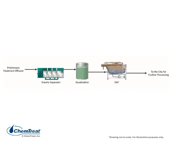
Optimum wastewater treatment methods will vary depending on the impurities within a wastewater stream. However, primary treatment is needed to remove solids and O&G for many applications. These steps often lower TOC, BOD, and COD to some extent. A common treatment scheme is shown below.
Figure 8.1. A common wastewater pretreatment schematic.
In some applications, waste streams may go through a preliminary screening step (rotary filters, bar screens, etc.) for large contaminant removal prior to downstream treatment. This step is more common for raw water makeup, where the influent may have logs, trash, and other sizeable debris.
Figure 8.1 illustrates a rectangular settling basin with several chambers. The ability of such units to remove particles is determined by Stokes’ Law. Heavier suspended solids such as sand and grit will easily settle under gravity’s influence, but smaller particles can remain in suspension for long periods. Accordingly, a primary clarifier may be necessary for additional solids removal. A brief review of clarification fundamentals follows.
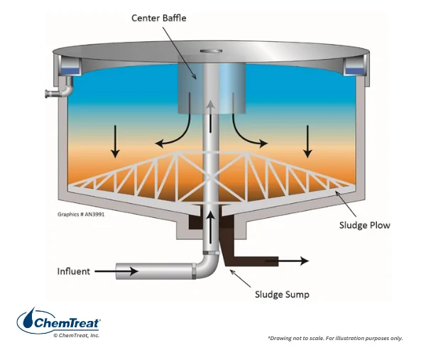
Figure 8.2. A primary wastewater clarifier.
In this particular design, coagulant injection to the clarifier influent neutralizes the typical negative charges on suspended solids. This water enters the main body of the clarifier, where the flocculated solids settle. Periodic sludge blowdown is necessary to remove accumulated solids.
Many wastewaters contain some amount of O&G that can foul downstream equipment. Several well-established techniques are available to reduce O&G concentrations.
Oil and Grease Removal
Often, much O&G is free-floating. Straightforward processes are available to remove this material, including American Petroleum Industry (API) separators, parallel plate interceptors (PPI), and corrugated plate interceptors (CPI). We will examine the API and PPI processes to illustrate fundamental oil removal mechanisms.
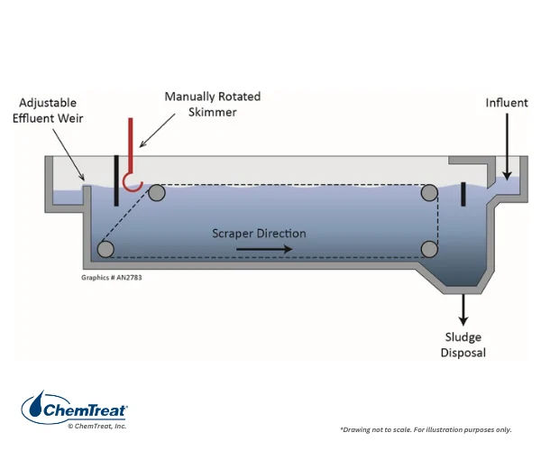
API Separator
Figure 8.3. An API oil/water separator.
As water flows through the vessel, free oil rises and moves along the surface to a rotating skimmer. The skimmed oil flows to a separate vessel for periodic disposal, typically by a specialty firm that takes the oily waste off site. Heavier solids within the separator settle and accumulate at the bottom of the unit, where a scraper system drags the material to a wet well for periodic blowdown.
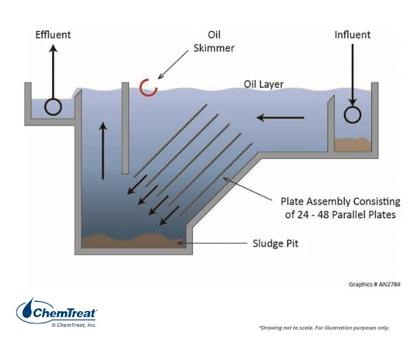
In PPI separators, oily water flows upwards through corrugated or parallel plates.
Figure 8.4. Schematic of a parallel plate interceptor.
The plates enhance separation of free oil and suspended solids. The oil coalesces and moves up the plate surfaces, while the solids agglomerate and settle in the sludge pit. A potential issue with plate separators is that solids can accumulate on the plates and reduce unit efficiency. Plate fouling may require regular maintenance cleanings.
Because basic oil/water separation is a mechanical process, chemical treatment is usually not recommended, as chemistry changes could negatively influence performance.
Second Stage of Primary Treatment
Dissolved Air Flotation
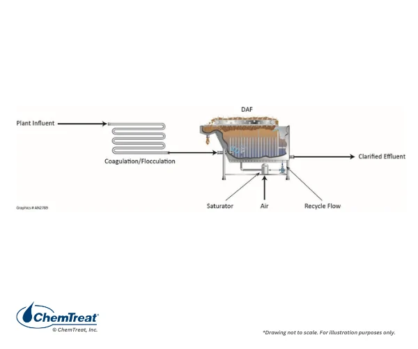
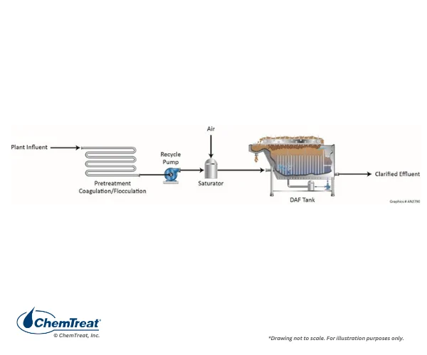
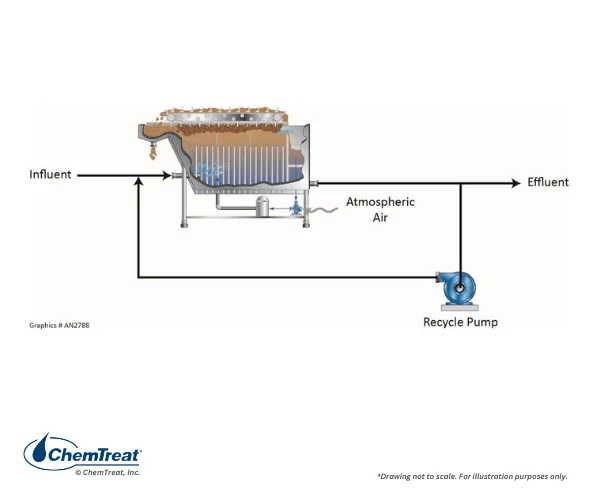
Frequently, an additional step is necessary to remove oily residue from wastewaters. Air flotation technology provides this treatment. The leading method and focus of this section is dissolved air flotation (DAF), but flotation technology also includes dissolved gas flotation (DGF), induced gas flotation (IGF), and, to a lesser extent, suspended air flotation (SAF). Two common DAF designs, the recycle air injection and full-flow air injection configurations, are shown below.
Figure 8.5.a. DAF with air injection to the recycle line.
Figure 8.5.b. DAF with air injection to the influent line.
Injected air generates many small bubbles that attach to emulsified particles and small suspended solids, causing them to float to the surface. From there, the solids are collected for disposal. A brief examination of the individual components of a DAF unit follows.
Coagulant/Flocculant Addition
Coagulant/flocculant treatment of the DAF influent is common to produce moderately larger particles that more readily attract microbubbles. Chemical feed must be carefully monitored and controlled to produce optimum floc size, as large flocs (>100 µm) may be deleterious.
Coagulation and Flocculation Basics 10-Minute Tech Series
The DAF flotation chamber may be circular or rectangular. In either case, the chamber is equipped with two functional zones: the reaction zone and the clarification zone. The reaction zone provides conditions for the suspended particles to contact and adhere to air bubbles. The clarification zone provides quiescent conditions for the air/particle agglomerates to rise to the surface. Some DAFs are designed with inclined plates to enhance solids separation.
Recycle vs. Full Flow Air Injection
DAF units have a recycle line, whose flow, depending on system design, may range from 30 percent to near maximum. Most designs have air injection into the recycle loop. The typical recycle stream pressure range is 30 to 90 psig, so that the stream releases air bubbles when it enters the DAF vessel. The rising bubbles often exhibit a “whitewater” effect that is clearly visible at the surface. Flotation creates a surface layer of oily solids that concentrates and thickens as it flows down the length of the chamber.
Full-flow pressurization systems have air injection to the DAF inlet. This design limits the feed pressure to approximately 50 psig, which reduces the amount of air entering the solution (vs. the recycle configuration). A potential concern is that full-flow pressurization creates turbulent conditions in the flotation cell which, in systems with coagulant/flocculant feed, may damage the flocs.
Air Injection Mechanisms
The air injection or air saturation system should be designed to provide the required amount of air in the form (bubble size) needed, such that a minimum amount of recycle flow is required. A common configuration, known as open-end air saturation, is shown below. Open-end air saturation includes atmospheric air suction and a recycle pump configured to handle water with entrained air. This design operates at a lower pressure than dead-end air saturation systems.
Figure 8.6. Air injection to the recycle stream.
Relief valves minimize pressure buildup.
Dead-End Air Saturation
A variation of the above design is dead-end air saturation. In these systems, compressed air is injected into a pressure vessel to form an air cushion. Over time, the air dissolves in the circulating water. This design is common for industrial water treatment, and it generates smaller microbubbles in a larger quantity than open-end saturation systems.
Additional DAF Design and Operating Details
Bubble Size and Air-to-Solids Ratio
Experience indicates that optimum conditions for liquid/solids separation occurs with microbubble diameters within a range of 10–100 microns, with most bubbles ranging between 40–80 µm. The gas/solid contacting sequence can occur by adsorption, adhesion, trapping, interception, and inertia. The air-to-solids (A:S) ratio is the ratio of entrained air versus the suspended solids mass entering the flotation chamber. A:S ratios are influenced by impurity characteristics (TSS density) and the chemical treatment method. Typical A:S ratios are between:
Low = 0.01 pound/day air:1 pound/day TSS
High = 0.40 pound/day air:1 pound/day TSS
One cubic foot of air at standard temperature and pressure weighs approximately 0.0807 lbs.
Recycle Rate
The recycle rate depends on air solubility and concentration of solids in the waste flow; the recycle rate can vary from 10–100% of the influent flow. Air saturation efficiency is better at lower recycle rates. As a rule of thumb, recycle rate is proportional to TSS. For an influent TSS of 1,000 ppm, an optimum recycle range might be 30–50%. At TSS of 2,000 ppm, the recycle rate might be as high as 100%.
Typical Load – DAF Clarification
Conventional DAF surface load:
Between 1.5 and 7.5 gpm/ft2, can be as high as 16 gpm/ft2. Most commonly it is below 5 gpm/ft2
Solids load between 0.30 to 2.0 lb/ft2·hr
Temperature
Water temperature influences viscosity and coagulation reactions. High temperature water may be problematic in some treatment applications such as those for rendering and refining. As with other physical and chemical parameters, temperature must be considered during project design.
Bottom Rakes
Heavy solids settle at the bottle of the flotation chamber and must be periodically removed. The DAF has bottom skimmers or rakes to remove solids from the flotation cell. The solids are disposed elsewhere.
Surface Skimmers
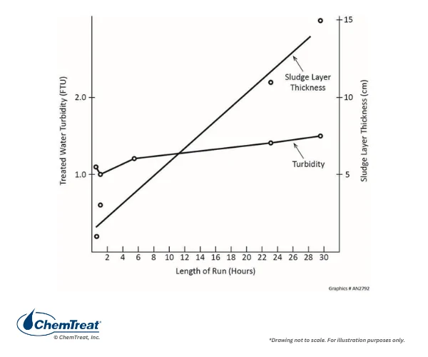
The final major item is the surface skimmer, which removes floating debris. The most common system is a chain-driven flight conveyor with paddles and a variable speed, timer-operated drive mechanism. The variable speed design allows for enhanced control of the floating layer thickness and effluent TSS.
The floating layer will remain stable for relatively long periods without impacting DAF effluent turbidity. The chart below outlines treated water turbidity and sludge layer thickness versus time.
Figure 8.7. DAF effluent turbidity as a function of time and sludge layer thickness.
The proper sludge blanket thickness is a function of the manufacturer’s recommendations, nature of the solids, flow rate, and desired results. Output may be limited by the sludge handling system capabilities.
Heavy Metals Treatment Methods
An introductory section of this chapter emphasized the very low limits for metals discharge concentrations. The common method for heavy metals removal is precipitation, either as hydroxide or sulfide.
Several alkaline compounds are available for hydroxide precipitation. These include lime (Ca(OH)2), caustic (NaOH), soda ash (Na2CO3), and magnesium hydroxide (Mg(OH)2).
Advantages of hydroxide precipitation include:
Ease of automation
Low cost
The process does not utilize or generate highly toxic compounds, as compared to sulfide precipitation, although caustic and lime must be handled with care.
Some disadvantages exist, including:
Difficult-to-remove multiple metals per variable solubilities as a function of pH. (This is illustrated in the next figure.)
May be ineffective on complexed metals, i.e., metals attached to either natural or artificial chelating agents.
High sludge volume
Metals more easily leach from hydroxide precipitates than sulfide precipitates.
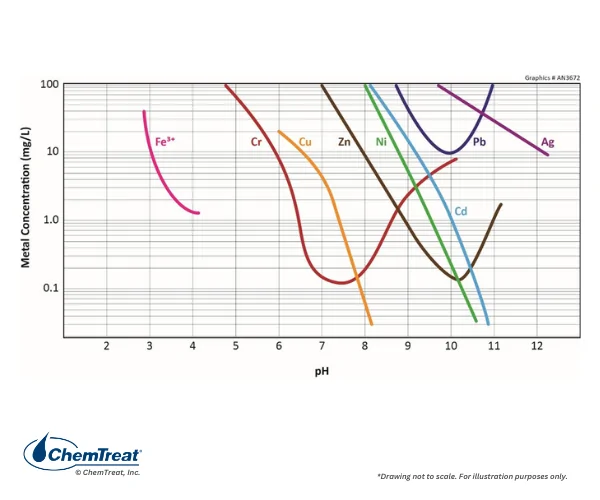
The following chart shows the optimum pH for hydroxide precipitation of many of the metals listed in Table 1-1.
Figure 8.8. Influence of pH on metals precipitation.
Close examination of this chart reveals several important details. First, the pH for minimum solubility of each metal covers a wide range. Secondly, some metals, and most noticeably chromium, zinc, and lead are amphoteric, meaning that solubility increases at both low and high pH, with an optimum point in-between. (Copper and cadmium also exhibit amphoteric properties, which are not shown on the graph.) Thirdly, hydroxide precipitation is much more effective for some metals than others. For example, compare nickel and cadmium to lead, noting that this is a semi-logarithmic graph.
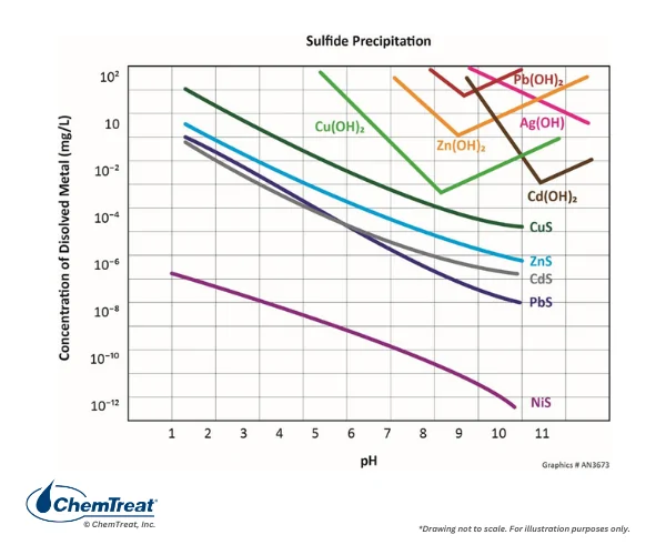
An answer to some of the hydroxide precipitation concerns (with caveats) is sulfide precipitation, as outlined in Figure 8.9.
Figure 8.9. A comparison of sulfide vs. hydroxide solubilities for several heavy metals.
Sulfide forms highly insoluble compounds with many metals, and although not shown in Figure 8.9, mercuric sulfide (HgS) is the least soluble of all the precipitates. In many cases, the metal-sulfide bond is so strong that the reaction will extract even chelated metals.
In the past, inorganic sodium and ferrous sulfides were the common compounds to generate precipitates in a clarifier or reaction vessel. However, this chemistry is not without issues. Some inorganic sulfides are quite toxic and must be handled with extreme care. Excess sulfide residuals in the clarifier sludge can impart hazardous characteristics. And, if the pH drops below 8 in the treatment process, malodorous hydrogen sulfide may evolve. Finally, the sulfide-metal reaction can be so rapid, e.g., with mercury, that the finely-sized precipitates may escape with the clarifier effluent.
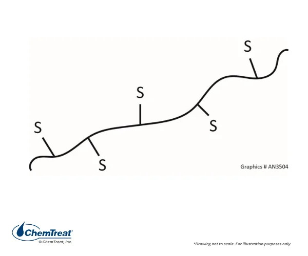
An answer to these issues has come with the development of flocculating polymers that contain sulfide groups.
Figure 8.10. Schematic of a polymer chain with sulfide groups.
The polymers are non-toxic, bind strongly with metals, and depart the clarifier with other sludge. One of the first uses for these compounds was mercury removal from wet flue gas desulfurization (WFGD) waste streams at coal-fired power plants.
Selenium Removal
Another problematic element is selenium. Selenium is a non-metal that is an essential nutrient for humans in very small concentrations, but, being directly below sulfur in the periodic table, can cause animal and human health concerns if it replaces sulfur in some metabolic pathways. Selenium does not undergo precipitation reactions as shown in the previous section. The element can exist in four different oxidation states: -2, 0, +4, and +6. Like sulfur, it readily bonds with oxygen, with the common anions being selenite (SeO32-) and selenate (SeO42-). Selenite is water-soluble but has a strong adsorption affinity to soil that greatly that reduces mobility. Elemental selenium (Se0) exists in crystalline form and is usually incorporated in soil particles. Selenide (Se2-) can occur as metal selenides (similar to metal sulfides), which tend to be deposited in the bottom sediments of water bodies, or as organic compounds (primarily as dimethylselenide).
One potential method for selenium control is wetland treatment. Wetlands act as a biofilter to remove organic matter, pathogens, metals, and nutrients, such as nitrogen and phosphorus. Wastewater that has already received primary and secondary biological treatment may be a good candidate for wetlands conditioning, as the lower pollutant loadings enhance treatment viability. However, this technology offers several disadvantages, including the large footprint, a potentially long pipeline to either a natural or artificially-constructed wetland, cost, environmental permitting issues, etc.
Heretofore, the EPA’s best available technology (BAT) for selenium removal is adsorption of selenite and selenate on an organic substrate, where microorganisms then convert the compounds to elemental selenium retained by the microbes. Periodically, the substrate must be removed and replaced with fresh material. Installation and operation of these systems incur considerable capital and operating costs.
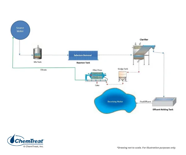
Non-biological alternatives such as reverse osmosis (RO), nanofiltration (NF), and ion exchange are cost prohibitive, but the ChemTreat SeQuester® technology offers a physical-chemical, specialized precipitation alternative. The equipment can be retrofitted into existing systems.
Figure 8.11. General schematic, ChemTreat selenium removal process.
The physical/chemical aspect of the technology allows for straightforward adjustment as dictated by process flow fluctuations. The chemistry effectively removes selenium and, also, captures other metals and metalloids, including arsenic, mercury, and molybdenum. The precipitates come out in downstream clarifier systems that include a filter press for sludge dewatering. Data from Toxicity Characteristic Leaching Procedure (TCLP) tests have demonstrated that the dewatered sludge is quite stable and can be landfilled as non-hazardous waste.
A Non-Biological Process for Selenium Removal From Industrial Wastewater
Many industrial processes generate wastewater with significant organic content. Examples include sugar, paper, pharmaceuticals, solvents, petrochemicals, raw, intermediate, and finished refinery products, and others. Many of these compounds are directly toxic to aquatic organisms or may deplete the oxygen concentration in the receiving water body.
Natural microbiological treatment processes have been utilized for decades to treat organics in wastewater streams at municipal and industrial facilities. The next sections examine several mature technologies and compare them to modern treatment methods, which have evolved to provide high efficiency with a small footprint.
The Fundamental Biological Process
Biological wastewater treatment employs natural microorganisms, primarily bacteria, to convert organic material into additional bacteria, carbon dioxide, and water.
Generally, some fraction of the organic carbon is oxidized to carbon dioxide, while the remaining fraction is converted to new bacteria. Typically, 1 pound of BOD generates roughly ½ pound of bacteria solids. In some cases, because the bacteria are natural and not hazardous to human health, they can be disposed of in a landfill or supplied as a fertilizer for non-edible vegetation.
Wastewater treatment bacteria require food, nitrogen (principally as ammonia), and phosphorus (principally as orthophosphate), generally in the ratio of 100:5:1 C:N:P, to thrive. Many wastewaters, and especially municipal supplies, have sufficient nitrogen and phosphorus. In others, supplemental nitrogen in the form of aqueous ammonia or urea can meet the nitrogen requirements. Phosphoric acid is a common additive for supplemental phosphorus.
Biological Wastewater Treatment Systems
In years past, attached growth systems such as trickling filters were popular for wastewater treatment. Now, more modern technologies like membrane bioreactors have emerged. To better understand these systems, it is helpful to first examine the well-known activated sludge process.
Activated Sludge Wastewater Treatment
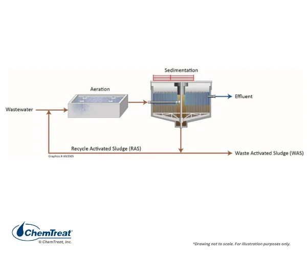
Activated sludge treatment is perhaps the most common suspended growth biological system. A simplified diagram is shown below.
Figure 8.12. Schematic of the activated sludge process.
Wastewater enters the aeration chamber, where the bacteria consume the organic material and nutrients. Aeration chambers are typically long, rectangular vessels with the influent at one end and the effluent at the opposite end. Generally large design volumes provide sufficient retention time for the bacteria to be effective. Basins are typically equipped with several aerators strategically placed to distribute oxygen and provide mixing throughout the chamber.
Clarification of the bacteria/water slurry, known as “mixed liquor,” produces a bacterial sludge and a clear effluent. The recycle activated sludge (RAS) returns the bulk of the sludge to the aeration vessel to replenish the bacteria. The waste activated sludge (WAS) stream is necessary for system purge. Generally, the WAS flow rate is adjusted to match the bacterial reproduction rate while RAS rates are typically held constant based on some fraction of the inlet flow rate.
Important clarifier process control instrumentation and measurements include:
Inlet flow meter to detect and respond to surges
RAS and WAS flow meters to monitor recycle and wasting rates, in part to determine basin residence time
Inlet and outlet turbidity
Process alkalinity, pH, dissolved oxygen (D.O.), BOD5, nitrogen, and phosphorus
Influent and effluent nitrogen and phosphorous
Slurry solids ratio V/Vo (Normal is a 30-minute settling time)
Sludge Volume Index (SVI) (Normal is a 30-minute settling time)
Manual or electronic sludge depth measurements
The optimum aeration basin D.O. concentration is 2–4 mg/L. Operators can sequence surface aerators or raise or lower blower speed to maintain this range. Aerator failures should be repaired promptly, as the loss of air can allow septic zones to develop. Microorganisms thrive within a relatively narrow pH window, with a common range being 6.5–8.5. Alkalinity, nitrogen, and phosphorus measurements are important to ensure that the organisms receive the proper food and nutrients, and are also important to track effluent concentrations. Typical nutrient discharge guidelines are <0.5 mg/L, although they may be lower, especially if the discharge is to a receiving body of water designated as “impaired” from previous water chemistry problems.
WAS flow control is important to help establish and maintain the desired bacterial concentration. Trial-and-error adjustment is usually necessary, as every system is unique. Flow change calculations require the following daily analyses.
Mixed Liquor Suspended Solids (MLSS). A known volume of sample is filtered and dried, with measurement of the resulting filter pad weight increase .
Mixed Liquor Volatile Suspended Solids (MLVSS). The solids from the MLSS test are placed in a high-temperature oven. The carbon compounds, primarily bacteria, volatilize. The ratio of remaining solids vs MLSS allows calculation of the microbial content.
Integrated RAS/WAS flow balancing is also important. Plant operators must maintain a solids balance within the system to minimize formation of septic zones, but not so RAS-heavy that it starves the WAS of sufficient suspended solids for downstream sludge handling and dewatering.
Sludge Digestion
Several methods are possible for treatment and disposal of waste sludge. At plants in rural locations, it may be possible to directly apply the sludge to non-crop fields. More common is sludge digestion to reduce the volume, followed by sludge drying. Both aerobic and anaerobic sludge digestion processes are available.
Aerobic Digestion
WAS is transferred to an aerated tank with mixers. The decreased food supply induces death of some bacteria. As the dead bacteria decompose, the remaining bacteria consume the carbon. The process reduces sludge volume and stabilizes the material, making it easier to dewater.
Anaerobic Digestion
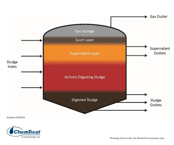
WAS is transferred to a sealed tank with precise temperature and pH control. In the absence of oxygen, the bacteria ferment and greatly decrease in volume. The process releases hydrogen sulfide (H2S) and methane (CH4). Some plants flare these gases, but others scrub the H2S and use the methane for boiler firing or as fuel for other equipment.
Figure 8.13. Schematic of an anaerobic digester.
Gas leakage from an anaerobic digester often generates public complaints about the “rotten egg” odor. Aerobic digestion is a relatively simple and forgiving process but produces no usable byproducts, while anaerobic digestion is more difficult to maintain and operate but can generate valuable energy. Treatment technologies have been developed to remove hydrogen sulfide from some process streams and alleviate odors.
Attached Growth Treatment Systems
Attached growth biological treatment is well known and has been around for decades. These systems contain internal fixed material to which bacteria adhere to form a biofilm. As water flows over the biofilm, the bacteria consume the organics. As with activated sludge, dead bacteria are removed from the wastewater by sedimentation and filtration. An early design was the “trickling filter” method. More modern technologies include:
Biological Aerated Filter (BAF)
Rotating Biological Contactor (RBC)
Membrane Bioreactor (MBR)
Traditionally, MBRs are considered suspended growth process systems. However, newer MBR systems may include attached growth components that can result in classification as an attached growth system.
Moving Bed Bioreactor (MBBR)
We will examine these newer technologies following a brief overview of the trickling bed design.
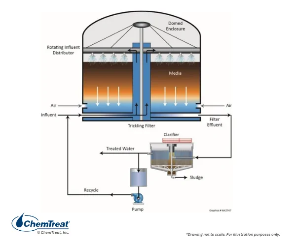
Figure 8.14. Trickling bed filter schematic.
A trickling filter is simply a tank filled with loosely packed gravel or plastic media where the raw wastewater is sprayed evenly on top of the bed and allowed to trickle through to a collection system at the bottom. Most designs include vent holes or slots cut into the side of the tank, with air drawn in by natural convection to flow counter-currently to the wastewater. Seventy-five percent BOD5 reduction is common with a trickling filter.
Biologically Aerated Filter (BAF)
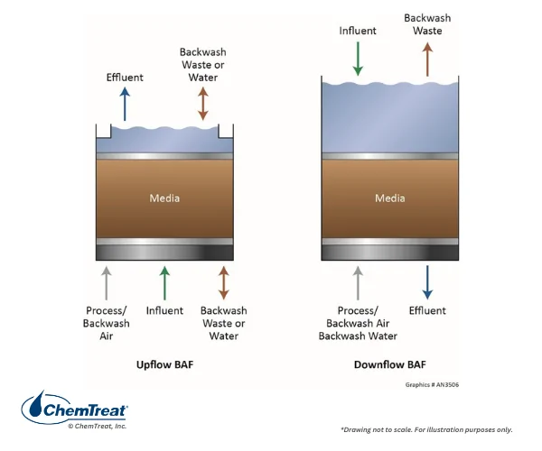
The two types of BAF styles, upflow and downflow, are outlined in Figure 8.15.
Figure 8.15a and b. General schematic of upflow and downflow BAFs.
In both systems, water passes through media of polystyrene or natural materials (clay, shale or stone), arranged in cells. Cells can be removed from service or restarted to accommodate varying flow volumes and influent water quality. Although the media provides some filtration for large particles, primary filtration and impurity (organic carbon and ammonia) reduction comes from the microorganisms attached to the media. Air is injected at the bottom of the unit to provide sufficient oxygen. As Figure 8.15 indicates, in upflow designs the air and wastewater travel co-currently, while in the downflow configuration, the flow is counter-current. Each offers its own advantages. Upflow units can handle higher influent flow rates than downflow designs, and do not tend to form air pockets, as the water sweeps the air in the direction it naturally wants to travel. Run times are longer in this design. The air discharge is at the treated end of the vessel, and thus has a reduced concentration of odorous volatile compounds.
In downflow BAFs, nitrifying bacteria in the lower sections of the filter have a strong oxygen supply to convert ammonia to nitrates. The cells can be backwashed and flushed thoroughly during regular operation, and it utilizes a combination of increased water flow and air scouring during backwash to loosen and flush debris from the vessel.
An advantage of BAF technology over conventional secondary treatment is a much smaller footprint. This is true of the other methods outlined in the next sections. Furthermore, BAF units can handle wide variations in water flow and temperature. Automated systems reduce manpower requirements for operation and maintenance, but operators must be fully trained on all aspects of the control system.
In some cases, BAF effluent is of sufficient quality to be immediately discharged, while at times additional treatment by disc filters or a clarifier may be needed.
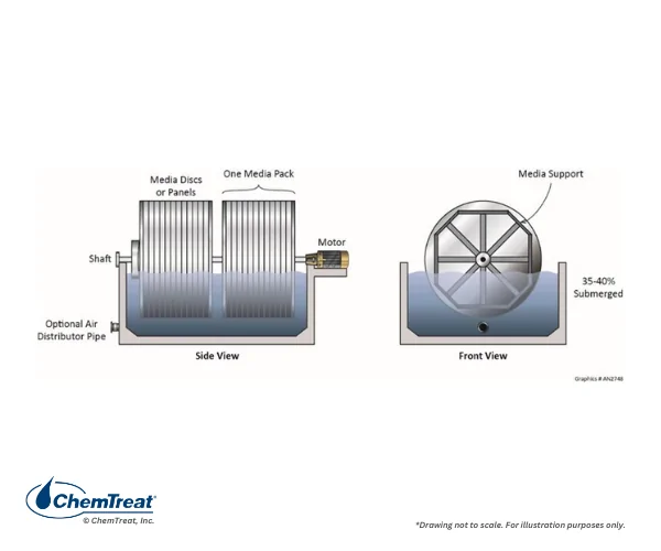
Rotating Biological Contactor (RBC)
In an RBC, the media consists of many closely-spaced, plastic, corrugated disks aligned evenly along a central shaft. The disks rotate slowly through a vat of flowing wastewater, allowing the bacteria to be submerged for approximately half of the rotation period. As the bacteria rotate out of the wastewater, they are exposed to air and pick up the oxygen required to metabolize the organic material. As in the case of a trickling filter, approximately 75% BOD5 reduction is achievable.
Figure 8.16. RBC schematic.
RBCs have a small footprint and offer low initial cost, low energy consumption, and straightforward maintenance. However, they are marginally effective in removing the organics primarily responsible for BOD and COD, and during upsets may release suspended solids.
On-line cleaning is typically not a feature of these units, rather disk replacement is the process to restore efficiency.
Membrane Bioreactors
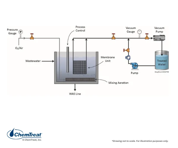
A membrane bioreactor (MBR) is an advanced method for removing soluble organic material from wastewater. However, in place of a settling basin or clarifier, MBRs utilize ultrafiltration or microfiltration membranes to screen suspended solids from the mixed liquor. MBR can produce a crystal-clear effluent. The most basic MBR design is shown in Figure 8.17.
Figure 8.17. Basic MBR schematic.
As with the other modern technologies described in this section, MBR has a much smaller footprint than a conventional activated sludge system with clarifier. Higher MLVSS concentrations are possible, which reduces the aeration tank volume. MBR process control techniques are similar to conventional activated sludge, where the operator adjusts the WAS flow rate to maintain the desired concentration of bacteria in the aeration tank.
These units can handle cycling duty much better than a conventional system. If the MBR must be offline for several days, microbe health can be maintained by feeding simple organic materials such as molasses.
Membrane cleaning is normally required when the trans-membrane pressure has increased by 5 kPA or so above baseline. A clean-in-place (CIP) system is common for this purpose. Correct chemical selection is important for effective cleanings. Bleach and caustic are typical for organic foulants, while for inorganic matter, including iron oxide particulates, a solution containing oxalic or citric acid may be best. In some instances, the spent cleaning solution may be considered hazardous waste. Consult with the membrane manufacturer for specific cleaning guidelines.
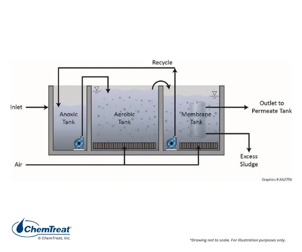
The following figure outlines a MBR configuration with external membrane filtration.
Figure 8.18. MBR with external filtration.
Note the anoxic zone in this figure. This reaction vessel is an added step for enhanced nitrogen species removal, and will be discussed in greater detail later.
Although MBR technology offers several advantages, membrane modules can be expensive and must usually be replaced every 5 to 10 years.
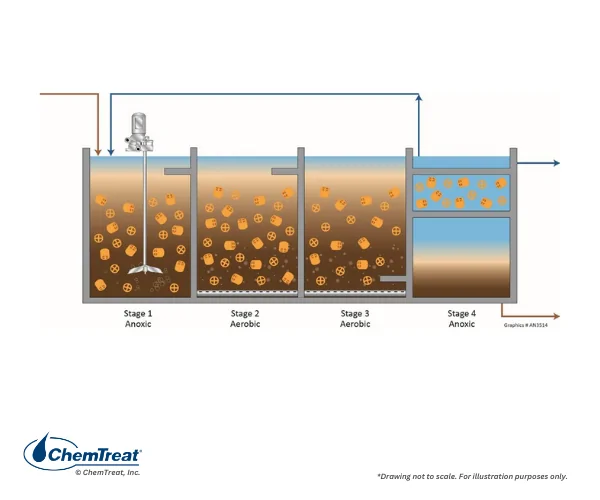
Moving Bed Biofilm Reactor (MBBR)
A MBBR contains mobile media (plastic disks) that move around in the reaction vessel. Microbes attach to the media and consume organics and nutrients as the media circulates. The large media surface area provides excellent interaction between the bacteria and impurities.
Figure 8.19. MBBR schematic with anoxic zone.
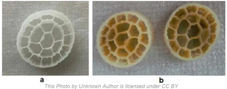
Figure 8.20 common MBBR media.
The reaction vessels often have mixers; although in aerated vessels, air injection helps keep the plastic carriers in constant motion. As with MBR, the process may have several stages to remove multiple impurities.
The bacteria can develop a positive electrostatic surface charge that is biologically regenerated as ammonium ions (NH4+). The ammonium ions are subsequently converted to nitrate. The optimum pH range for this biochemistry is 7.2–7.5.
While some MBBR designs have clarifiers for effluent polishing, membrane filtration is also viable. Either must be external to the reaction tanks.
Biological Nitrogen Removal
As outlined earlier, ammonia is a primary nutrient for the bacteria in biological treatment systems. However, the wastewater may contain more ammonia than the bacteria can remove, requiring additional nitrogen removal from the wastewater prior to discharge.
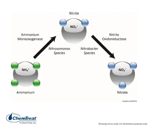
Nitrification
In many cases, converting ammonia to less-toxic nitrate (NO3–) may be all that is needed to meet ammonia discharge guidelines. Specialized bacteria drive this process.
Figure 8.21. The nitrification biochemistry process.
Most aerobic wastewater treatment systems can be configured to promote nitrification. The necessary conditions include:
Elevated concentrations of MLVSS. Nitrosomonas and Nitrobacter are slow-growing organisms that generally attach to the surface of heterotrophic bacteria. Long sludge retention times elevate MLVSS, allowing nitrifying bacteria to become established and thrive.
High concentrations of dissolved oxygen, which enhance the conversion to nitrite and then nitrate.
Sufficient bicarbonate alkalinity. The nitrification process creates acid that would inhibit the microbial process without the neutralizing influence of alkalinity. Additionally, nitrifying bacteria utilize the inorganic carbon of alkalinity as the food source.
Denitrification
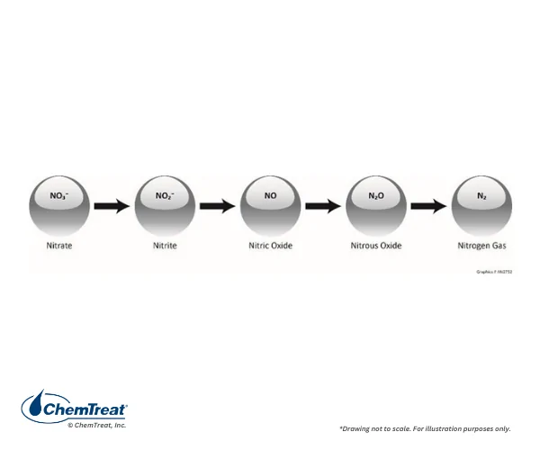
Depending on the sensitivity of the receiving body of water, discharge permits may require a low effluent total nitrogen concentration. In that case, the basic conversion of ammonia to nitrate may not be adequate for compliance. Via a step-wise process, with the aid of beneficial bacteria, nitrate can be converted to nitrogen gas that escapes to the atmosphere.
Figure 8.22. The step-wise process of nitrate conversion to elemental nitrogen.
Denitrification requires an extra step in the conventional aerobic process in both attached and suspended growth systems. The bacteria function in an “anoxic” environment, with a D.O. concentration close to zero.
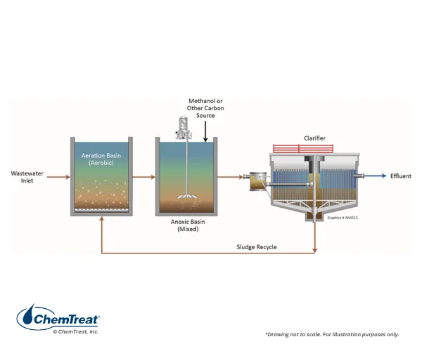
Figure 8.23. A common activated sludge system with denitrification.
In the anoxic tank, the bacteria extract oxygen from nitrate and initiate the reaction sequence shown in Figure 8.22. An organic food supplement such as methanol is required.
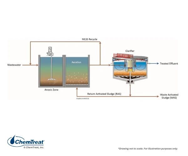
Some modern denitrification systems are of the Modified Ludzak-Ettinger (MLE) design. This arrangement places the anoxic tank ahead of the aerobic basin and incorporates a high-flow recycle stream from the aerobic basin back to the anoxic tank.
Figure 8.24. Schematic of the MLE process.
Organic carbon in the anoxic zone influent serves as food for the denitrifying bacteria, eliminating the need for artificial organic feed, such as methanol. The recycled MLSS contains the NO3/NO2 from ammonia conversion in the aeration basin and is recycled back to the anoxic basin for denitrification. Ultimately, the process reaches a steady state, which results in a relatively low effluent NO3/NO2 concentration.
Tertiary Treatment of Wastewater
Tertiary treatment improves wastewater quality to make it suitable for discharge to receiving streams or reuse in industrial water applications. The biological denitrification process described above is one example of tertiary treatment. Other processes include media filtration, activated carbon filtration, and disinfection.
Filtration
Media and activated carbon filtration methods may not be needed if particulate levels are below discharge limits, but if filtration is necessary, a thorough evaluation of effluent conditions is important to select the most effective technology.
Disinfection
For municipal wastewaters, disinfection to kill pathogens is necessary to prevent their release to the environment. Many industrial wastewaters may not contain pathogens, but if disinfection is required, primary methods include chlorination, treatment with hydrogen peroxide, and ultraviolet radiation exposure.
Chlorine
Chlorination is still very popular for wastewater disinfection. Most industries no longer use chlorine gas because of the hazards associated with elemental chlorine and handling of gas cylinders. Liquid bleach has emerged as the replacement because of simplified handling and transportation requirements in comparison to chlorine, with a caveat. Industrial bleach has a 12.5 percent active concentration, so transportation costs can be significant to haul a product that is mostly water.
The residual oxidant concentration in many discharge permits is 0.2 mg/L, and sometimes much lower. Dechlorination with liquid sodium bisulfite or gaseous sulfur dioxide may be necessary. Dechlorination adds another level of complexity and cost to wastewater disinfection.
Hydrogen Peroxide
Hydrogen peroxide (H2O2) is a strong, fast-acting oxidizer and will react quickly to kill microorganisms including viruses and bacteria. H2O2 byproducts are oxygen and water, so effluent issues are non-existent. Disadvantages include complicated handling procedures and costly feed systems.
Ultraviolet Disinfection
Ultraviolet (UV) disinfection inactivates microorganisms. UV offers simplicity, avoids chemical handling, and does not produce any disinfection byproducts. However, the UV light must penetrate through the wastewater, which may be problematic for large volumes or if the water is cloudy. UV installations require weirs or gates to control the wastewater level and velocity.
Sludge Conditioning and Dewatering
Virtually all wastewater treatment systems produce a waste sludge that must be disposed of. In some cases, the sludge can be directly applied to fallow land to serve as nutrients for vegetation such as turf farms or golf courses. In other situations, the sludge must be converted to a dry product that can be landfilled. In some cases, sludge contains heavy metals that have been sequestered within the solids. Hazardous sludge processing can be complex, challenging, and expensive. Selection of the best technology for any application requires knowledge of the origin and constituents of the sludge as well as the final disposal requirements.
Conditioning
The primary method of sludge conditioning is thickening to prepare the sludge for dewatering. In many cases, the process is similar to that for conventional clarification, i.e., coagulation and flocculation.
The most common coagulants for sludge dewatering are lime and ferric chloride. However, other coagulants may be effective, such as aluminum sulfate, aluminum chlorohydrate (ACH), polyaluminum chloride (PAC), ferric sulfate, organic coagulants, and blends of organic/inorganic coagulants. As with clarification, coagulants neutralize the negative charge of the particulates.
Common wastewater flocculants have crosslinked structures to resist shearing during sludge dewatering. However, at times more conventional branched and linear flocculants may be cost effective. Crosslinked flocculants offer higher solids capture, producing a filtrate with lower TSS. Anionic flocculants may be more effective for inorganic sludge dewatering, while cationic flocculants may be better suited for organic sludge settling and dewatering.
Filter aids may assist with sludge preparation. The most common filter aids include diatomaceous earth, perlite, ash, coal, activated carbon, fiber (paper pulp), and sawdust. These materials create micro-channels in the sludge that adds structure to the filter cake, enhances drainage, and eases cake release from the filter medium.
Jar testing with the aid of a water treatment chemical supplier is very important for selecting the proper chemicals and dosages for efficient clarification and sludge conditioning. Once jar tests have confirmed proper chemistry, full-scale pilot testing will help identify the best feed points to ensure optimum mixing and contact time. Final treatment program selection is a function of several factors, including chemical treatment cost and ease of application balanced with optimal clarifier performance and sludge characteristics.
Sludge Dewatering Methods
For wastewater systems where sludge dewatering is required, optimizing the dewatering process is economically beneficial. Furthermore, poor sludge dewatering can potentially shut down the plant if the material is unfit for transportation or disposal. The following sections outline the most common sludge dewatering technologies.
Belt Press
A basic belt press schematic and actual unit operation are shown below.
Figure 8.25. Belt filter press schematic.
Gravity drains some water along the horizontal plane as the belt rotates. Additional water removal comes as the belt moves past the large roller and the smaller rollers compress the sludge. The properties of the solids here are most important and are dependent on proper clarifier operation and chemistry to maintain particulate integrity. The mechanical features of the belt filter such as hydraulic loading, belt speed and tension, roller compressive force, and belt water wash systems are also important factors.
Centrifuge
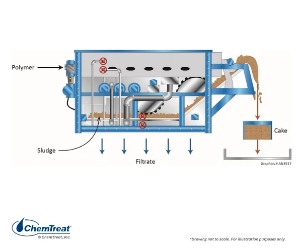
Centrifuges can be either continuous flow or batch flow. A common design is shown below.
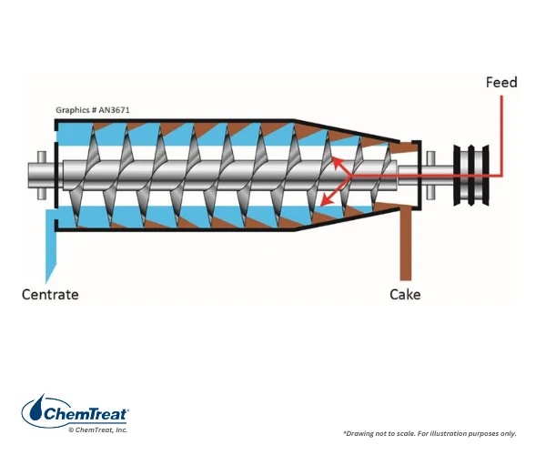
Figure 8.26. A “solid-bowl” centrifuge schematic. The blue represents the water volume while the conveyor is the helical screw in the center of the machine.
The rapid rotation of the centrifuge imparts a force 3,000–6,000 times greater than gravity to remove water from the solids. The cake is extracted at one end of the centrifuge and the water, known as concentrate, exits the opposite end.
As with other dewatering systems, sludge conditioning can improve centrifuge performance. Flocculant feed just before or just inside the centrifuge may be beneficial. Other mechanical adjustments can be made to pool volume, bowl speed, and conveyor speed.
Plate and Frame Filter Press (PFFP)
PFFP is a very common device that operates in batches.
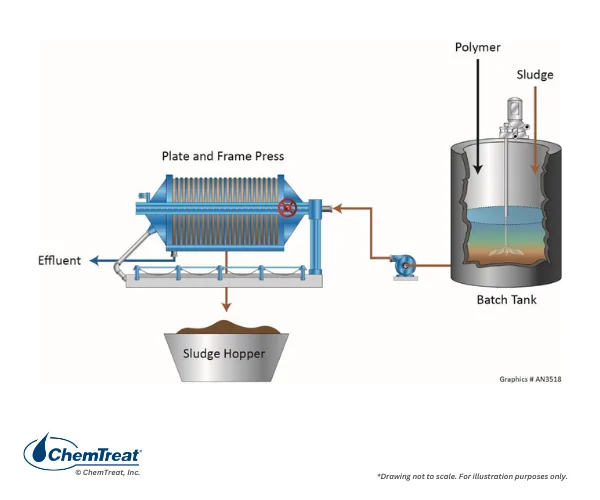
Figure 8.27. PFFP schematic.
The compartment contains many individual plates covered with filter cloth. Sludge is pumped into the vessel and fills the openings between the plates. Contrary to popular belief, mechanical pressure is not applied to the plates. Rather, as solids accumulate and close off the space between plates, the pressure increases and drives water through exit channels. The process continues until the maximum pump pressure is achieved and/or filtrate flow reaches a minimum. A common pressure range is 25 to 225 psig, depending on the application. Some systems are designed to increase flow and pressure gradually, as otherwise cloth blinding could result. Once the cycle reaches completion, the pressure is released and the plates are mechanically separated. The filter cake discharges into a hopper below for subsequent disposal.
PFFP is often the preferred method to treat sludge with poor dewatering characteristics. Coagulant, flocculant, or filter aid feed can enhance water drainage and improve cake release. For example, adding diatomaceous earth to oily sludge may reduce blinding of the filter cloth.
Some units are equipped with an air blow system to push out liquid sludge before plate separation. A regular maintenance procedure is cloth washing to remove solids that do not release during normal cake generation.
Vacuum Filters
The typical vacuum drum configuration is shown below.
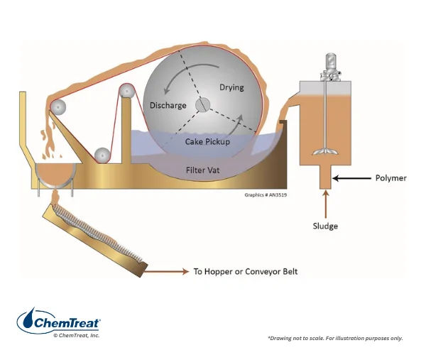
Figure 8.28. Vacuum drum schematic and photo.
The horizontal, perforated drum is covered with a filter cloth and separated into sections where vacuum is applied. As the drum rotates through the fluid in the vat, water is pulled inwards, and the solids accumulate on the filter cloth of the individual sections. Further rotation brings the cake to a scraper with a tight tolerance to the filter cloth so that the cake is removed and falls into a collection hopper. These hoppers are often equipped with a conveyor that moves the sludge to a larger holding area or truck loading facility. The sludge feed vessel has agitators to maintain a homogenous solids concentration, which is necessary to establish a consistent cake thickness.
Vacuum filter efficiency is often measured as pounds of dry sludge produced per hour per square foot of filtration area. Another common measurement is percent solids or percent moisture in the cake. As with other dewatering methods, feed of sludge conditioners upstream of the filter may enhance performance. Physical adjustments including changes to the vat level and drum rotational speed can also be employed to improve performance. Higher speeds will reduce the cake thickness and dewatering time, resulting in higher production in terms of filter surface area, but this change may produce a cake with higher moisture content. Reduced drum speed produces a thicker cake but might lower the production rate. Additional factors that influence performance include:
Sludge suspended solids concentration.
Sludge particle size and shape. (Very fine particles can sometimes plug the filter cloth).
Sludge compressibility and viscosity.
Applied vacuum. A “one size fits all” is not a good approach. The vacuum may need adjustment based on sludge compressibility and potential for cloth blinding.
Zero Liquid Discharge
Industrial plant discharge regulations have become increasingly stringent since the Clean Water Act (1972) was first introduced. As was noted earlier in this chapter, limits on some constituents such as heavy metals may be at low ppb concentrations, and even lower for especially hazardous elements such as mercury. Zero liquid discharge (ZLD) can help mitigate some of the uncertainty around wastewater effluent compliance. Additionally, some plants have adopted ZLD out of necessity due to current or near-future water shortages. Each step in a ZLD process generally becomes increasingly costly and maintenance-/labor-intensive. Rigorous system design and conscientious commitment by plant management towards staffing and operational details usually determines the success or failure of a project.
This section examines several of the most common ZLD configurations and illustrates some of the major issues in achieving ZLD. We also discuss near-zero ZLD systems, in which a final, small, discharge-compliant stream is generated, while valuable constituents in the recovered stream are recycled to a plant process.
ZLD Configurations
A notable industry with ZLD applications is combined cycle power generation. One configuration is shown below.
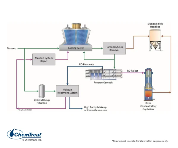
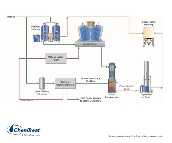
Figure 8.29. One of several viable ZLD configurations for a combined cycle power plant.
A key component of this process, as it is with several others, is a high-recovery reverse osmosis (RO) unit to recover approximately 90% of the discharge for return to the makeup water system. RO is a cost-effective technology to purify the bulk of the wastewater and greatly reduce the volume to the much more expensive downstream technologies.
Typically, the RO influent pH must be elevated with caustic feed to obtain such high recoveries. However, without pretreatment, pH adjustment would induce calcium and silicate precipitation in the RO membranes, quickly shutting down the unit. Accordingly, the configuration shown above has a sidestream clarifier to remove hardness and silica. Most of the clarifier effluent recycles to the cooling tower, but a bleed stream, which represents the cooling tower blowdown, is taken to the RO. The high-volume RO permeate is recycled to the makeup treatment system, while the much smaller RO reject stream receives final treatment in an evaporator/crystallizer (E/C). The solids from the E/C unit are blended with dried clarifier sludge for disposal.
In systems such as these, evaporator/crystallizers have the highest materials and operating costs. Even with a small influent volume, E/Cs can be large and complex systems to operate. Feed of seed crystals is common to induce precipitation of fresh solids on the crystals rather than internal surfaces.
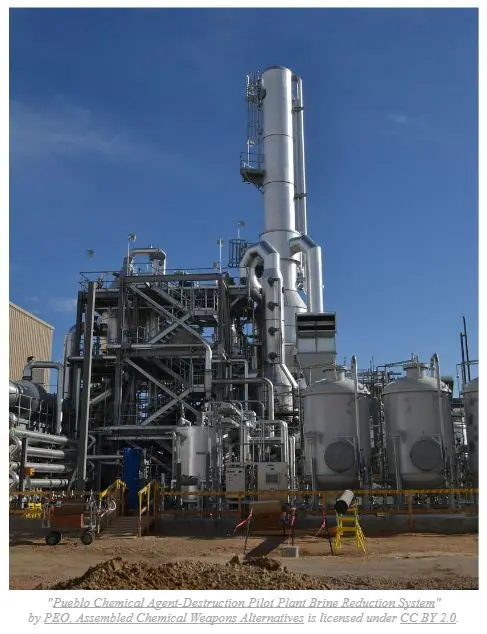
Figure 8.30. A brine concentrator.
E/C units typically must be fabricated from specialty metals to minimize corrosion from the highly-concentrated salts. Energy requirements are considerable due to the boiling point rise as salt solutions become more concentrated. A technology that has been developed to lower energy costs is the application of a mechanical vacuum to the evaporator to lower the boiling point. Energy costs for the vacuum pumps are not influenced by boiling point rise.
In a variation of the final water disposal from Figure 8.29 and 8.31 below, a spray pond replaces the evaporator/crystallizer at a combined cycle power plant in a semi-arid location in the western U.S. RO recovery is 90 percent, and the spray pond has enough capacity, admittedly with a large footprint, to provide the necessary average evaporation to handle periodic heavy precipitation events. Also noteworthy in this case is that the RO has upstream microfiltration to protect the membranes from particulate fouling.
An alternative to Figure 8.29 is shown below.
Figure 8.31. A variation of the system shown in Figure 8.29.
In this configuration, the clarifier/softener treats the cooling tower makeup, not the blowdown. This arrangement allows for higher cooling tower cycles of concentration and a corresponding lower blowdown rate. (Refer to Figure 6.24 in Chapter 6 for an illustration of this relationship.) Lower blowdown volume may eliminate the need for RO, with direct feed to the brine concentrator. However, softening clarification produces large amounts of sludge.
Numerous design and operational lessons-learned are available from past ZLD installations. Frequent shortcomings or issues include:
Many evaporator/crystallizers are undersized due to the high cost of this equipment.
Scale and foam control in evaporator/crystallizers presents significant challenges, including selection of effective and cost-efficient treatment programs.
Reliable ZLD operation requires highly-trained personnel and sophisticated process control systems.
A common need is a large storage or evaporation pond to collect wastewater when the ZLD system is down for either a scheduled or unscheduled outage.
Near-Zero ZLD
The examples highlighted in the figures above illustrate complete ZLD to eliminate all liquid water discharge except perhaps for slight moisture within dewatered sludge. Configuration adjustments can provide near-zero ZLD in which the system conserves and recycles water, but also recovers a valuable byproduct for reuse in the plant. RO is utilized to concentrate the salt solution to a much smaller volume, followed by electrolysis of the concentrated solution to generate caustic and sulfuric acid. The remaining liquid is a small, purified stream. Another application involves concentrating organic compounds into a smaller volume, with follow-up impurity removal by granular activated carbon (GAC) or perhaps a specialty ion-exchange resin that can then be taken to a permitted disposal facility.
The examples in this section outline several evolving technologies to further reduce discharge of harmful impurities to the environment. But ZLD design, installation, and operation require rigorous attention to detail from beginning to end. The cost of failure can be astronomical.
Conclusion
As this chapter has emphasized, industrial wastewater quality can be highly variable, which requires flexibility in treatment design. A further, and very interesting, example is provided in Appendix 8-1, which discusses a process that is often not mentioned in general technical books but is important to many industries. The key point is that for any application, due diligence and rigorous review of project design and needs is necessary to select the proper wastewater treatment procedure. Field tests and sometimes pilot tests are also important items, which can be coordinated with a reputable water treatment firm.
Find Custom Wastewater Treatment Solutions With ChemTreat
ChemTreat is committed to providing expert water treatment solutions. Our innovative and customized wastewater treatment solutions help businesses across a variety of industries control and monitor wastewater while meeting changing environmental regulations. Contact ChemTreat to get in touch with your local representative to learn how ChemTreat can help your business today.
Ross, Charles C., Brandon M. Smith, and G. Edward Valentine. “Rethinking dissolved air flotation (DAF) design for industrial pretreatment.” WEF and Purdue University Industrial Wastes Technical Conference. 2000.
Tchobanoglous, G., Burton, F. L., & Stensel, H. D. (2004). Wastewater engineering: Treatment and Reuse (Vol. 4). McGraw-Hill Publishing Company Limited.
Edzwald, J. K., & Haarhoff, J. (2012). Dissolved air flotation for water clarification. McGraw-Hill. Buecker, B., Belden, J., and I. Mello, “Iron and Peroxide Chemistry: A Common Weapon for Combating Several Wastewater Treatment Plant Issues”; WaterWorld, November 2019.
K. Boudreaux, “ZLDS Training“; ChemTreat Technical Training Presentation.
Information provided by Alfonso Salinas, ChemTreat.
S. Ottewell, “Wastewater Technology: Developments Decrease Discharge”; Chemical Processing Morning Briefing, March 15, 2022.
Appendix 8-1
Paint Detackification
Introduction
For many years, humans have painted or otherwise coated materials and structures to protect them from atmospheric corrosion and degradation, and often for aesthetics as well. Painting of many equipment components is done in spray booths, where ambient conditions including temperature, humidity, and dust levels are carefully controlled to optimize the painting process. However, anywhere from 20–70% of the paint does not contact the target and is considered overspray. Water washing is common to remove this overspray, for if the paint is not properly treated, aka “detackified,” it can quickly clog recirculating pumps and pipes, degrade exhaust air quality, and increase fire and explosion hazards. If paint is detackified but the wash water is not properly treated, the water can serve as a food source for pathogenic or odor-causing bacteria. This appendix outlines the unique but very important wastewater treatment issues for the many painting facilities around the globe.
Paint Spray Booth Design
Numerous paint booth designs exist, but this appendix examines two: sidedraft and downdraft. The sidedraft booth is the oldest and most common design.
Figure 8.1.1. Schematic of a sidedraft booth.
Air enters one side of the booth and exhausts at the other side. The paint-laden air passes through a water curtain that scrubs the overspray, with discharge to a sump. The sump discharges to a paint collection unit for paint removal, with clean water return to the spray booth.
Downdraft booths are designed for larger applications and are used exclusively in automobile assembly plants.
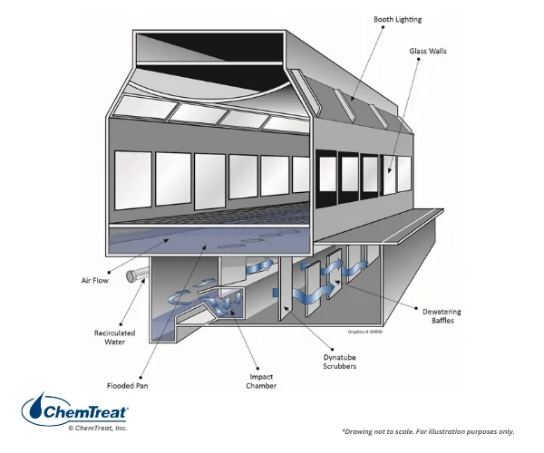
Figure 8.1.2. Downdraft booth design.
In this design, filtered air enters from the ceiling and exits through slots in the floor. Water enters the booth from both sides and exits though floor slots. The intimate air/water contact scrubs the paint. Clean air exhausts through stacks, while the paint-laden water flows from the bottom of the booth to the treatment unit. As with sidedraft designs, the clean water is returned to the booth.
Wastewater Treatment
Because many varieties of paint exist, with different chemistries, a “one-size-fits-all” approach to detackification is not possible. Consider lacquer-type paints that cure by organic solvent loss when exposed to the atmosphere. Caustic addition to the water often improves scrubbing, as it reacts with the binder in the lacquer to form a soap that acts as a surfactant to emulsify the solvent. The emulsified solvent separates from the paint, allowing the paint to harden as a dispersed suspended floc during the detackification reaction, while the emulsified solvent is removed with the system water. Sodium or potassium hydroxide are the typical caustic source.
Metal salts from inorganic coagulants of iron or aluminum can serve to detackify both air-reactive paints and non-air-reactive, solvent-borne paints. For proper detackification, the pH should be increased to an 8–10 range. The metal salts react with esters in the paints to form a metal soap that speeds up the curing process. Additionally, a pin floc and associated complex of precipitated metal hydroxide with microbubbles of entrapped air develops. The paint can then be readily separated from the water. In general, waterborne paint is not sticky and does not need to be detackified, however, it must be removed from the booth system water. Treatment with a high molecular weight (HMW) flocculant is common to remove the pin floc. Anionic flocculants are typical for solvent-borne paints and cationic flocculants for waterborne paints. The required metal salt dosage may vary widely depending on the application.
If detackification is difficult, enhancement of spray water dispersion chemistry may be necessary. This can be done by raising the alkalinity of the water, while taking care to stay within the required pH operating range. Soda ash (Na2CO3) and sodium metasilicate are common conditioning chemicals.
Acid colloids may be employed to detackify solvent-borne paints. These compounds have both hydrophobic and hydrophilic properties. They are soluble in acidic conditions but form a complex structure with increasing pH. Some acid colloids include cationized-starch, silica amine, silicate amine, and melamine formaldehyde. The hydrophobic ends of the molecules attach to paint droplets, while the hydrophilic ends bind with water. The paint droplets become coated with water and are no longer sticky. This treatment is most effective when the paint remains atomized and then disperses in water that has an elevated pH per alkalinity addition.
A modern detackifier consists of chitosan (a polymeric glucosamine) and a metal salt/cationized-starch. This formulation is considered “Green Technology” and is patented by several companies. Chitosan comes from crustaceans. The metal salt is typically aluminum-based, with the starch derived from corn. Due to high solution activity, the aluminum/starch composition performs well at a lower dosage.
Paint booth water is monitored to maintain the proper pH and alkalinity for the desired paint dispersion.
The detackification polymer is normally fed to the booth recirculating water. Polymer dosage is primarily dictated by the amount of paint overspray, type of paint, solvent-borne or waterborne paint, and paint booth design. Polymer feed during production is normal, however, polymer slug feed is possible for newly-filled systems, when painting is sporadic, and/or in systems where detackified paint is not regularly removed from the recirculation water with a sludge consolidator unit.
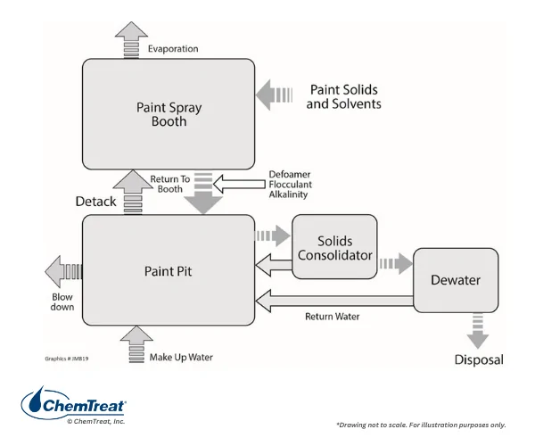
Per the above discussion, Figure 8.1.3 outlines the general schematic of paint detackification water treatment.
Figure 8.1.3. Paint booth water schematic.
Conclusion
This appendix is but one example of the many specialty wastewater treatment applications that exist at various industries. Careful evaluation and data collection is a must in choosing effective treatment programs.
About the Authors
Jean M. Gucciardi
ChemTreat Technical Staff Consultant, Retired
Jean Gucciardi worked in industrial water treatment for nearly four decades, focusing on influent, boiler, cooling, and wastewater applications. Gucciardi was published in multiple industry publications throughout her career. She earned a B.S. and an M.S. in Environmental Engineering from the University of Wisconsin.
David Marturana
Senior Technical Consultant
Dave Marturana has been working in industrial water treatment since 1981 and joined ChemTreat in 2008. He has a B.S. in Chemical Engineering and is a licensed Professional Engineer in the Commonwealth of Pennsylvania. An applications consultant for influent and industrial effluent water treatment, Marturana has extensive expertise in coagulant and flocculant selection and optimization, primary and biological wastewater treatment, municipal graywater treatment, and sludge dewatering applications.
Maria Muniz
Director, Polymer & Pretreatment
Maria Muniz, Director, Polymer & Pretreatment, has been working in industrial and wastewater treatment since 1990, focusing on the petrochemical, steel, automotive, and food & beverage industries. Her application expertise includes solid-liquid separation, secondary treatment, and solids management and dewatering in light and heavy industries both in the US and internationally.
Alfonso Salinas
Director, Polymer Technology
Alfonso Salinas, Director, Polymer Technology, specializes in the design, construction, and operation of water and wastewater treatment processes and has direct experience in treatment facilities with flow capacity between 1 and 114 mgd. His areas of expertise also include biological, coagulation-flocculation, sludge dewatering, metals removal, filtration, ion exchange, boilers and cooling, jar testing, and lab testing. Salinas holds a B.S. in Civil Engineering and an M.Sc. in Environmental Engineering.
Acknowledgements
The ChemTreat Water Essentials Handbook would not have been possible without the contributions of many people. See the full list of contributors.

 Introduction to Industrial Wastewater Treatment Methods