Demineralizers are an often neglected component of industrial water treatment. Because demineralizer malfunction can cause issues with downstream processes, it is important to identify and treat problems early to reduce negative impact to your operations.
What is Demineralization?
Demineralization is a process for high-purity water production using ion exchange. It is commonly used in industries such as semiconductor manufacturing and pharmaceuticals as well as in high-pressure boiler feedwater applications. Demineralization is achieved using demineralizers, which are chemicals used to remove minerals from water.
Demineralizer Process Flow Overview
The schematic below shows the process flow from a cation unit all the way to a mixed bed polisher. (A basic demineralization stream would only include a cation unit and an anion unit.)
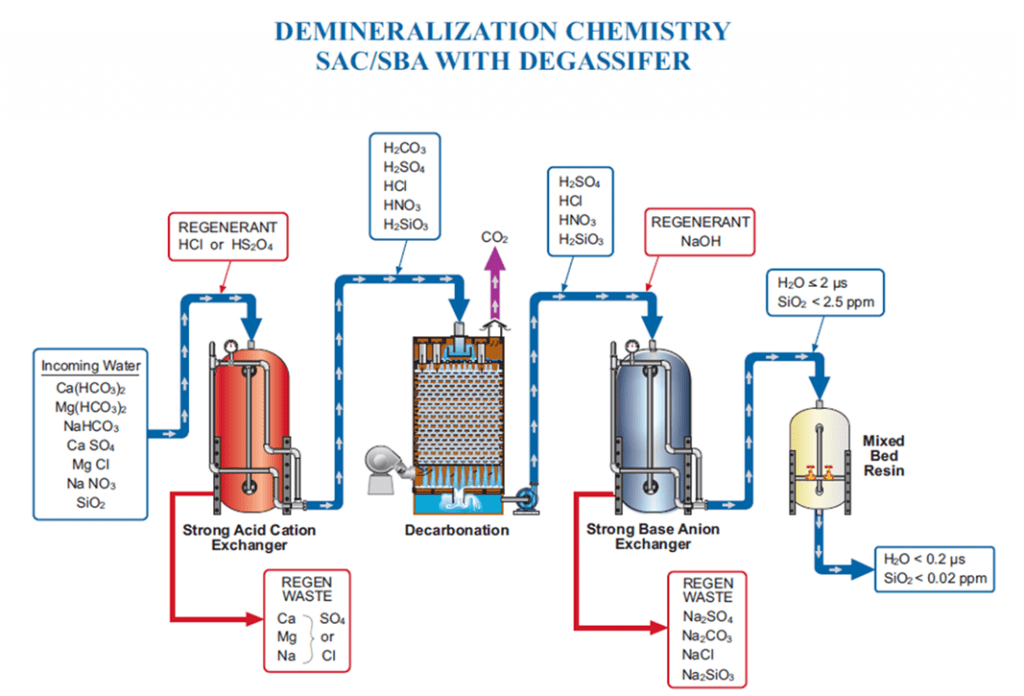
Inlet water is full of ions: cations such as calcium, magnesium, sodium, and potassium, and anions such as phosphate, alkalinity, sulfate, chloride, nitrate, and silica. Demineralizer systems remove these ions from water intended for high-purity processes.
Cations are first removed from the water in the cation unit. Hydrogen ions are exchanged from the resin beads for the cations in the inflowing water, lowering pH. The remaining anions combine with hydrogen ions to form their corresponding acids and hydrogen sulfide (H2S) if present.
The water then passes through a degassifier to strip carbon dioxide (CO2) from the water and expel it to help reduce anionic loading to the anion unit.
Finally, the anion unit removes anions from the water through ion exchange, releasing hydroxide ions into the anion stream. Water coming out of the anion unit will be relatively pure, likely under 2 µS conductivity, and contain only low levels of sodium and silica. Some applications, particularly high-pressure boilers, may need to run the water through a mixed bed polisher for further treatment.
Two Primary Demineralizer Issues
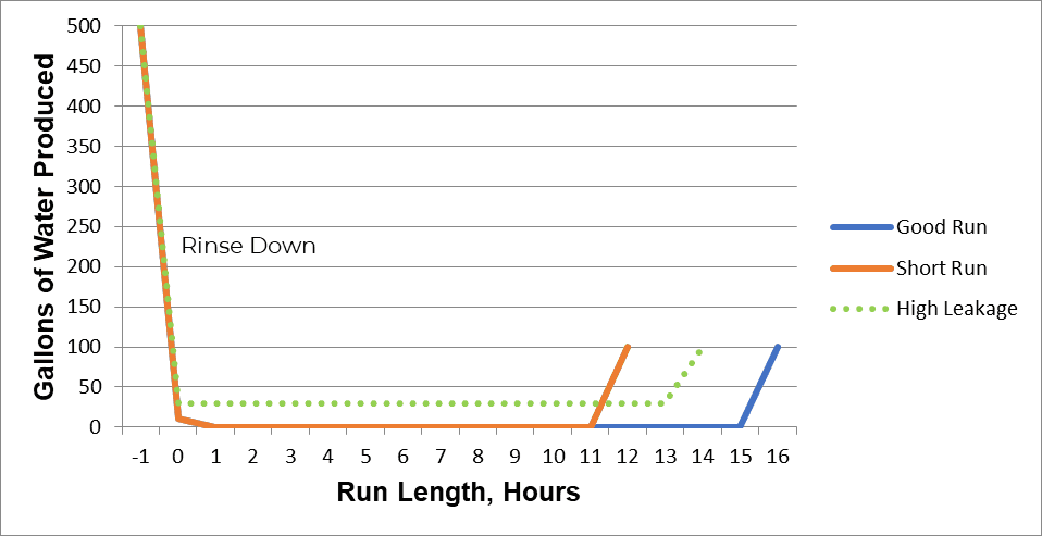
1. Short Runs
A short run indicates low throughput. The quality of the produced water can be acceptable, but conductivity and/or silica breakthrough occurs early, and the system produces fewer gallons of process water between regenerations.
2. High Leakage
High leakage refers to worsening water quality throughout the service cycle. This could include higher sodium or silica levels, depending on the cause.
Demineralizer Troubleshooting Best Practices
The Importance of Keeping Records
Recordkeeping is a key component of troubleshooting demineralizers. Trending key metrics lays the groundwork for diagnosing system issues.
At a minimum, we recommend keeping track of the following data:
- Run length after every regeneration: how many gallons of water are produced on a given train between regenerations.
- Rinse length time: how long anion units or mixed beds take to rinse down to spec.
- pH and conductivity of the raw water, cation effluent, and anion effluent.
- Regular silica analysis of anion effluent: investing in on-line sodium or silica analyzers can be a great way to troubleshoot system issues.
- Annual resin analysis: Send core samples to an analytical laboratory to help determine what may be contributing to resin fouling (e.g., organics or silt).
- Quarterly source water samples. Source waters can change, particularly rivers and surface water, so we recommend regularly monitoring samples to track any shifts in water composition.
- Annual vessel inspection to ensure vessel internals are in good shape, laterals and screens are intact, etc.
Troubleshooting Short Runs
Changes in Feedwater Quality
Feedwater quality can vary over the course of the year. A demineralizer system is designed for a set number of ions, and conductivity changes will impact the system throughput.
For the sake of simplicity, water with 100 µS conductivity has about half as many ions as water with 200 µS. Therefore, a demineralizer processing water with 200 µS conductivity will have approximately half the throughput of a system processing water with a conductivity of 100 µS. This shift in throughput can be mistakenly interpreted as a short run, but it does not actually indicate a problem in the system.
Low source water conductivity can often mask poor resin performance because the throughputs are longer. As the conductivity increases, it can cause potential performance issues, so ensuring proper demineralizer operation is important to maintaining system health.
Resin Loss
Resin loss leads to reduced water production, causing short runs. It may be triggered by backwashing at too high a flow rate, which lifts resin and solids out of the unit.
We recommend checking resin levels every time the vessel is opened. Resin levels should be approximately 6 inches below your regenerant distributor (check schematics to confirm the position of the regenerant laterals). If resin is lost, it has to go somewhere: check where the backwash discharges to determine if any resin has been lost.
Seasonal Backwash Rates
Water density varies with temperature (cold water is denser than warm water), so backwash rates may need to change with the seasons. A single, set backwash flow rate could starve the demineralizer in the summer or provide excess flow in winter. Depending on where your facility is located, the ideal backwash flow for the summer months may be much higher than what is required for winter. The ideal backwash for most resins is 50% bed expansion.
Fouling
When backwashing does not occur as needed, solids from the feedwater build up in the resin, causing mud or silt fouling, also known as total suspended solids (TSS) fouling. Fouling can also be caused by issues with an upstream clarifier. In general, influent water to cation units should have no more than 5 Ntu of TSS.
Mud fouling can be treated by:
- Extending the backwash or increasing the backwash flow rate to expand the bed as much as possible without losing resin.
- Air scouring or using an air lance to break up clumps of mud in the bed before backwashing.
- Applying surfactants to clean resin (typically while equipment is off-line).
Channeling
Solids and silt fouling can lead to channeling, the preferential flow through a portion of the resin bed. When mud or silt and solids foul a resin bed, water will flow through the path of least resistance, creating large canyons or cracks. Insufficient backwashing is a major cause of channeling.
To test for channeling, perform a manual regeneration and let the unit backwash. After backwashing, skip all other regeneration steps until the fast rinse. If your water quality returns, your bed was channeled, and the resin may need to be cleaned.
A Quick Note about Packed Beds
Packed bed demineralizers make excellent quality water with lower leakage than co-current regenerated units. However, the resin is packed between two plates in these vessels, leaving no room for it to expand during backwash to remove solids. Packed beds require external backwash tanks where resin can be removed from the service vessel to be fluffed and cleaned of solids every 1–4 months. If your system does not have a backwash tank, ensure your feedwater is high quality, with a target Silt-Density Index (SDI) of less than 5.
Resin Degradation
Chemical Damage: Resin can chemically degrade, causing short runs and higher leakage. If a free chlorine residual is carried from the front of the plant through the clarifier to the demineralizer system, the cation resin becomes susceptible to chlorine damage. Dechlorinating water before it enters the cation units is best practice for mitigating this issue.
Temperature Damage: Anion resin is susceptible to damage caused by high temperatures. Styrenic resins have a temperature limit of 140°F (for Type I resin) or 95–105°F (for Type II resin). Acrylic resins have a temperature limit of approximately 90–95°F. Be aware of these limits and monitor the ambient temperature of influent water as caustic is heated for regeneration.
Troubleshooting Increased Leakage
Poor Regenerations
One major cause of short runs and high leakage is poor regeneration. Units are designed for a set amount of acid and caustic feed. If acid or caustic is underfed during a regeneration, this can result in both short runs and higher leakage. Acid and caustic must be fed at the correct dosages and concentrations.
Sulfuric acid is typically fed at 4-10 lbs. of acid per cubic foot of resin, and caustic is fed at 3–8 lbs. per cubic foot of anion resin. The recommended concentrations are 1–5% for acid and approximately 4% for caustic.
Troubleshooting with Elution Studies
Elution studies measure regenerant concentrations in and out of the vessel with a hydrometer to determine the concentration. Regenerant values out of the vessel should slowly approach the concentration going into the vessel.
Important Note: When conducting the hydrometer measurement, temperature should also be measured, as it will increase during the exothermic reaction of acid and caustic. The hydrometer reading will need to be corrected with the use of a temperature compensation chart.
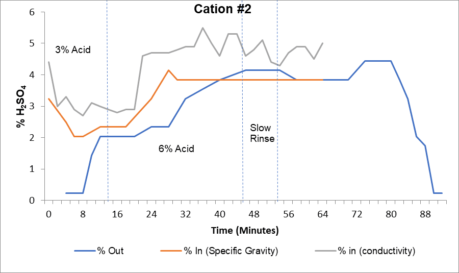
The curve above provides an example of elution study results for a cation unit. The gray line represents the percent acid into the cation unit measured by a high-range conductivity meter. The orange line represents the percent acid measured by a hydrometer, and the blue line shows percent acid coming out of the vessel.
This regeneration required a 3% acid step and a 6% acid step. The high-range conductivity probe showed target acid concentrations were being reached, but manual hydrometer sampling indicated that acid was underfed by at least 1% in each step. After calibrating the conductivity meter, the plant achieved proper operational levels.
Hardness Fouling in Cation Resin
Hardness fouling occurs when hardness precipitates as calcium sulfate in the resin bed, causing high leakage and short runs. When using sulfuric acid, it is important to pay close attention to the acid concentration in the system. Sulfuric acid regeneration causes calcium and barium from the resin to react with the sulfates to form and precipitate calcium sulfate (gypsum). Step-wise acid addition can prevent hardness precipitation.
Starting at a lower acid concentration, feed 1–2% sulfuric acid to regenerate the bed, then increase the concentration to 2–5% to achieve good regeneration without the risk of calcium sulfate precipitation. Proper acid concentrations for step-wise acid addition should always be calculated; always consult your resin manufacturer prior to changing acid concentrations.
Troubleshooting
Calcium sulfate precipitation will appear as white, snowy flakes in the acid outlet sample. This indicates one of two things:
1. The dilution flow rate is too slow, or
2. The first step acid injection is too high (potential hardness fouling in the resin bed)
Organic Fouling
Organic fouling is a common issue for demineralizers, particularly in systems that use surface water for makeup. It causes long anion rinse times and shorter runs.
Troubleshooting with Anion Unit Elution Studies
If you suspect your system is fouled with organics, monitor the outlet color during caustic injection. If it darkens to a tea-like color, approaching 8–12 on the VCS scale, the anion resin is probably organically fouled.
What Causes Organic Fouling?
Surface waters are loaded with tannins and lignins, which are long-chain organic acid molecules. Negatively charged, these molecules behave like anions in the feedwater and will attach to the anion resin. Once bound to positively charged functional groups on the anion resin, the long chain molecules get wrapped up in the resin and block other ion exchange sites.
When caustic is added during regeneration, sodium ions bond to the remaining sites on the negatively charged organic chain molecules. These will slowly elute off during the fast rinse and extend rinse times. As a result, long rinse times are also a good indicator of organic fouling.
Note: The removal of organics from the anion resin will not be 100% effective. Typically, the percentage of remaining organics in Type I resin is 70%. Over time, these organics accumulate, and a caustic brine squeeze will need to be performed to remove them.
Treating Organic Fouling: Caustic Brine Squeeze
A caustic brine squeeze is a preventative method for anion resin organic fouling.
For influent water with high organics, such as river water, a caustic brine squeeze may need to occur at least 2–4 times a year.
Caustic Brine Squeeze Procedure
(This is a brief overview of the procedure; consult with your water treatment provider before performing a caustic brine squeeze to ensure all necessary steps are taken.)
1. Inject 2–3% caustic at 95°F for 20 minutes, then flush the caustic from the unit
2. Inject with 8–10% brine or sodium chloride and soak the resin for 40 minutes
3. Repeat this process until the color of the cleaning solution lightens to a tea-like color
Iron Fouling
Iron can foul cation resin, resulting in short runs. High iron concentrations associated with well water, ferric chloride, or ferric sulfate use can result in iron precipitation in the resin bed. Iron fouling is fairly easy to detect with an off-site resin sample evaluation. Samples should be taken every time a vessel is open and at least once per year.
Iron-fouled systems can be treated with iron cleaners such as ChemTreat’s RL2016.
Coagulant Fouling
Coagulants that can foul cation resin include DADMAC or organic coagulants like polyamine. Organic coagulants have a high positive charge and a high molecular weight. The positive charge will attach to cation resin and bind, essentially irreversibly. DADMAC dosage must be strictly controlled because DADMAC fouling is also often irreversible and overfeed can foul the cation resin downstream.
DADMAC fouling causes a “plastic bag” effect, as if a plastic bag were caught up in the resin, preventing larger ions from moving through the bed and causing hardness leakage. If coagulant fouling is suspected, the methylene blue dye test can be run on a sample sent off-site. The off-site laboratory test will evaluate whether the resin uptakes the dye, which would indicate coagulant fouling.
Internal Vessel Inspections
It is best practice to inspect vessel internals annually. During these inspections, a core resin sample should be taken, and the following items noted:
Internal lining
- Is it intact? Or is it cracked or bubbled?
- Is there slime or biological fouling present?
- Is there a brown (iron) or white (calcium) coating along the inside?
Distributors
- Are the laterals and distributors even?
- Are spray hole orientations correct?
- Are screen wrappings intact?
- Is corrosion occurring?
The top of the resin bed
- Are solids obvious and present?
- Is there channeling in the bed?
- Are any oily substances on the bed?
- Mark the height of the resin; does resin need to be added?
Does the shape of the bed have an even, flat top?
Decarbonator Problems
Decarbonators tend to be neglected more frequently than demineralizers. These systems remove CO2 and H2S, and, if functioning improperly, will cause short runs. If a decarbonator issue is suspected, check the CO2 concentrations in and out of the unit to determine the efficiency of CO2 removal.
Decarbonators act like giant air scrubbers. If their filters are failing or pulling in dirty air, they can contribute to downstream anion unit fouling. Additional problems can include incorrect spray distribution, improper air flow, and a collapsed or biologically fouled packing element.
Three Things to Look for when Troubleshooting Mixed Bed Issues
Mixed beds should be rinsed down to approximately 0.1 or 0.2 µS within an hour. A longer rinse time indicates a problem with the system. In these cases, there are three main things to check.
1. Incomplete separation of cation and anion resin after backwash: There should be a clear, sharp separation between the two resins. If the separation is poor, cross-contamination may occur during regeneration, causing extended rinse downtime.
2. Poor mix step: Air flow during the mix step should be violent and achieve target air flow.
3. Failure to properly drain: The bed should be drained down before the mix to the correct level. If draining too high or too low, a good mix will not occur.
Need Help Troubleshooting Your Demineralizers?
ChemTreat is here to help you troubleshoot your demineralizers and associated water systems. We can help you analyze the resin, and our technical experts and local team can pinpoint issues and create a treatment plan best suited to the needs of your facility.
As with all other technologies, due diligence is necessary to determine the feasibility for utilizing these methods. It is always important to consult your equipment manuals and guides and seek guidance from your local water treatment representative to address your specific needs.