Introduction to Industrial Boilers and Steam Generation Systems
Steam is a fundamental and extensively utilized energy transfer medium. Steam systems generate electricity, provide energy for industrial heat exchangers, produce mechanical energy for propulsion of naval and merchant vessels, and serve as the energy source for commercial and residential heating; the list goes on and on.
Steam boilers range in size from those for small businesses to some that are multiple stories in height to produce electricity. Operating pressures can range from just over atmospheric to 2,800 psi in large drum boilers and 4,500 psi or perhaps even greater in cutting-edge ultra-supercritical units.
Table of Contents
Introduction to Industrial Boilers and Steam Generation Systems
Boiler and Steam System Design
Specialty Boilers
Steam Generation Chemistry
The Evolution of Power Boiler Water Treatment
Internal Treatment Methods for Industrial Steam Generators
Boiler Layup
Returning the Boiler to Service
Chemical Cleaning of Steam Generators
Steam Systems and Chemistry
Steam Chemistry
Additional Superheater/Reheater Issues
Appendix 4-1
Appendix 4-2
References
Boiler and Steam System Design
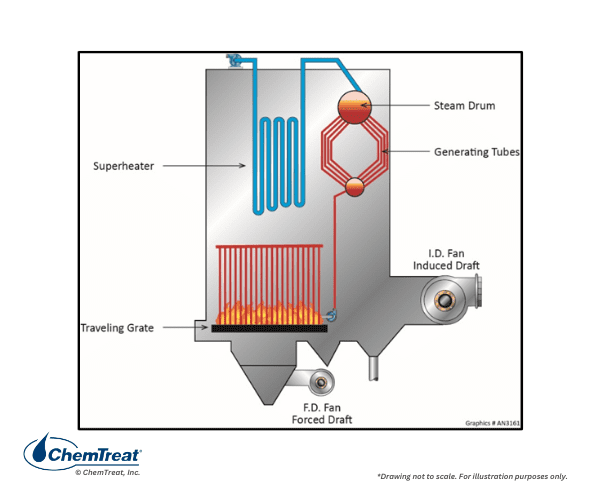
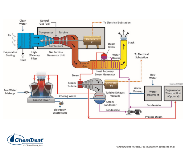
While all steam generators have similarities, one major point of differentiation is whether the steam is utilized solely for process and equipment heating or if it drives turbines for power or mechanical energy production. As will be outlined, this difference has significant impacts on several factors, including guidelines for makeup water purity, selection of pre-boiler and boiler chemical treatment programs, and steam purity requirements. Figure 4.1 is a basic flow chart of a common industrial steam generating system.
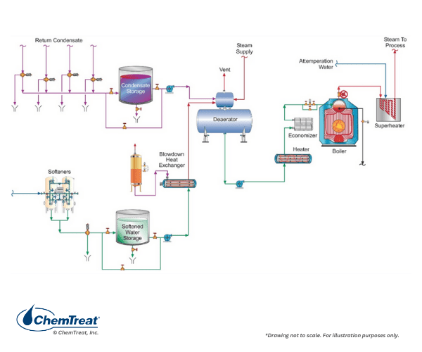
Key components of this system are:
- Makeup water treatment to remove harmful impurities. Techniques range from simple softening, as shown here, to high-purity demineralized water. The extent of makeup treatment depends largely on system pressure but includes other factors, as will be outlined in this chapter and has already been mentioned in Chapter 3.
- Condensate return from various plant processes.
- A mechanical deaerator to remove non-condensable gases, most notably dissolved oxygen, from the makeup water and condensate return. A deaerator also serves as a feedwater heater and includes a storage vessel for reserve feedwater capacity.
- Feedwater pump(s) to boost the pressure above the boiler pressure.
- A steam generator, often including a superheater
- Steam users that may include turbines, reaction vessels, re-boilers, or many other varieties of heat exchangers.
Steam Basics
Consider an everyday example of an open container of water at sea level. Here, at standard atmospheric pressure (14.7 psia), the water boils at a temperature of 212°F. The energy needed to raise the temperature to 212°F is termed “sensible heat.” Additional heating does not increase the temperature but instead converts liquid water to steam. This is known as the latent heat of vaporization, which is almost 1,150 Btu/lbm for water at sea level. 212°F is the saturation temperature at these conditions.
If this container were equipped with a sealable lid (a common household example is a pressure cooker), the boiling point temperature would increase. For example, doubling the pressure inside the vessel raises the boiling point temperature to 249°F. This principle is the fundamental basis behind industrial and power boilers producing steam at pressures and temperatures above atmospheric.
The thermodynamic properties of steam have been very carefully compiled into steam tables that may be found in numerous references, including #1, #2, and #5 of this chapter. Figure 4.3 below offers a representative example of data in the steam tables.
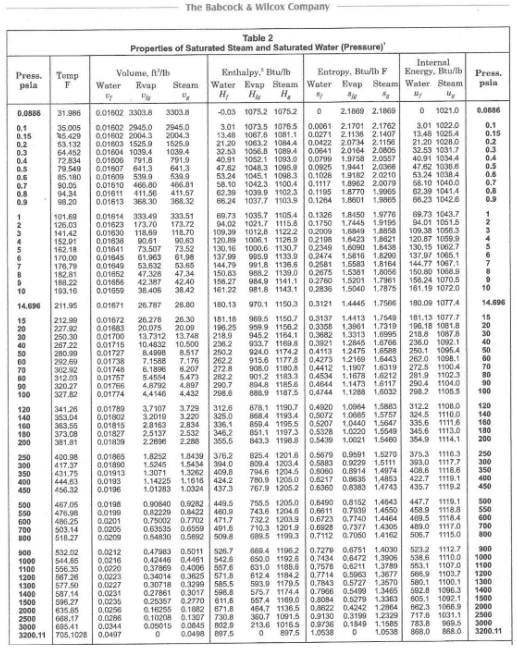
The first two columns are baseline values for temperature and pressure. Following are the corresponding data for both liquid and vapor of specific volume (υ), enthalpy (H, the total energy content), entropy (s), and internal energy (μ). The latter is that energy comprised of atomic and molecular rotations and vibrations. It represents the core energy of the fluid. Enthalpy has internal energy as a foundation but is a derived value that accounts for the total energy available. Enthalpy is much handier for energy transfer calculations than internal energy alone.
Entropy is often a difficult concept to grasp, but a common explanation is that every system proceeds in the direction of increased disorder. If a perfume bottle is opened, the aroma will permeate a room. A hot cup of coffee radiates heat to the kitchen, not vice versa. Energy is required to return the state of a process to a previous state, and for any process, the total entropy always increases. A classic example is a refrigerator. The entropy of the refrigerator contents decreases as they are chilled, but the increase in overall entropy change due to heat transfer from the compressor to its surroundings is greater (ΔS>0). In steam applications, the entropy values from the tables can be utilized to calculate the amount of energy unavailable to do work. Common factors that increase entropy include friction, heat escaping the boundary of a system, and others.
An item to note from Figure 4.3 is the increase in saturation temperature with increasing pressure. For example, the boiling point of water at 2,500 psi is 668.17°F. Temperature and pressure have an important impact on the choice of boiler water treatment chemistry, as will be discussed in later sections. Another aspect is that water and steam become a single phase at supercritical pressure/temperature (3,200 psi/705°F) and above. There can be no steam/liquid separation in a drum-type boiler, so that design does not work for supercritical conditions. Once-through boilers are the only choice.
For many steam applications, especially power units that drive turbines, saturated steam with no superheating is unacceptable, as condensation would occur once the steam begins doing work. Water droplets can severely damage turbine blades. Thus, many boilers are equipped with superheaters to raise steam temperatures well above saturation. The steam tables also include data for superheated steam, an example of which is shown in Figure 4.4.
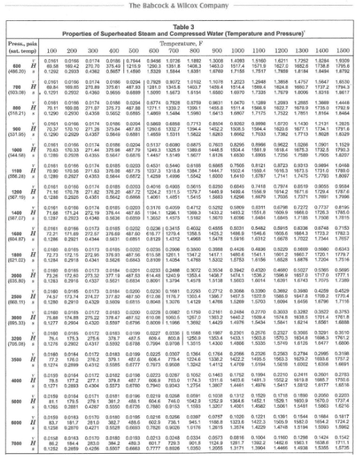
Essentially, only superheat energy is utilized in power turbines, with the latent heat being discarded to the environment at the turbine exhaust. Improved thermodynamic efficiency has led to the growth of co-generation and combined cycle plants, which utilize much of the latent heat.
Steam Generator Design Aspects
Boilers, of course, require heat and water to make steam. The heat source is generally fuel combustion within the furnace, but in some applications, combustion takes place apart from the steam generator, and the exhaust heat then generates steam in a separate boiler. A common example is a combined cycle power generator, where a portion of the total power is produced by a gas turbine similar to a jet engine. The turbine exhaust gas provides energy for heat recovery steam generators (HRSGs). The heat source can also be hot gases from a chemical process referred to as waste heat boilers and discussed more later.
Three types of heat transfer occur in conventional boilers. In the furnace itself, a major heat transfer mechanism is radiant energy. Convective heating is the second form of energy transfer, wherein the hot gases, via physical movement generated by the boiler fans, contact the boiler tubes and additional heat exchangers such as superheaters, economizers, and so forth. Convective heating is the primary energy transfer mechanism for combined cycle HRSGs, although many HRSGs are equipped with duct burners to provide additional heat during times of peak demand. The third form of heat transfer is conduction, which is the transfer of kinetic energy from molecule to molecule within boiler tubes from the furnace side to the water/steam side.
Boilers are typically categorized by the following criteria:
- Function, e.g., process steam only or power turbine operation/co-generation
- Fuel type
- Waterwall or firetube arrangement
- Drum-type or once-through
- For drum-type boilers, natural or forced circulation
- Pressure
- Size/steaming rate
- Direct fired or powered with waste heat
Function: How the boilers are utilized and the service they perform. Do they supply steam just for process heating, or for turbines? Also, are the boilers stationary or mobile such as marine applications?
Fuel Type: Many industrial boilers are fired with natural gas. It burns more cleanly than other fossil fuels and has become inexpensive, subject to geopolitical factors. In the middle of the 20th century, coal-fired boiler construction was common, as coal was an inexpensive and plentiful fuel. Concerns about air and water emissions from coal-fired plants, coupled with economic issues, have led to a sharp decline in coal plant operation. Renewable energy has filled part of the gap in power production, with much of the remainder taken up by combined-cycle power generation that utilizes natural gas. Few units are oil-fired any longer and will not be considered in this chapter.
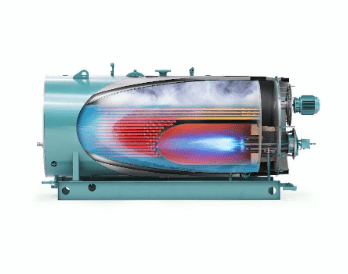
Fire- or watertube: In firetube boilers, the combustion gas flows through the tubes, which are surrounded by water contained in a shell. The opposite is true for watertube boilers, as the following diagrams indicate.
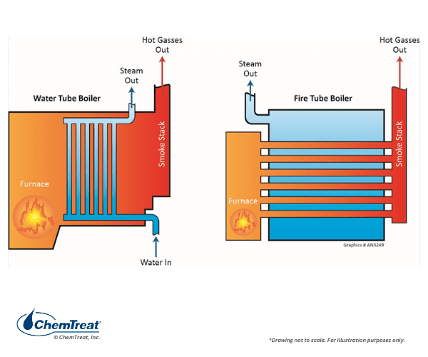
The large diameter tubes and short length of firetube boilers ensure low-pressure drop on the gas side. They are the oldest class of commercial boilers and were the basic design for steam locomotives of the 19th and early 20th centuries.
Firetube boilers are generally limited in pressure to 200 psi and a maximum of 20,000 pounds of steam production per hour. Watertube boilers can operate at much higher pressures and steam output, with steam temperatures up to 1,050°F or perhaps even higher in some advanced power designs.
Firetube boilers have a large volume of boiler water relative to steam production and so can store energy, which provides stable steaming rates and smooth operation. The furnaces may be internal or external. Many firetube units are still in operation. One of the most popular is the horizontal return tube (HRT) design, where the combustion space is a large firetube configuration at the bottom of the drum through which combustion gases pass and then turn at the back end of the furnace and return through straight tubes to the front of the boiler.
Firetube boilers are typically factory assembled, including burners, controls, fans, and feedwater pumps, all contained on one base as a package unit.
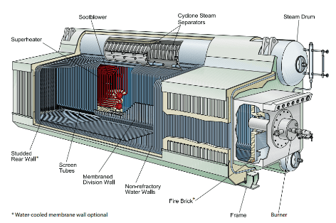
Higher-pressure boilers are almost always watertube design. The fluid flows through the “waterwall” tubes, with the radiant heat and hot gases confined to the tube exterior. Tubes can withstand much higher pressures than the external shell of firetube boilers. By far the most common design is the drum-type boiler with a basic configuration shown in the following two diagrams.
Waterwall tubes are typically fabricated into membrane panels that comprise the walls of the steam generator. A cutaway of this design is illustrated below.
Watertube boilers have a low boiler water volume relative to steaming rate as compared to firetube types. Accordingly, these boilers are more sensitive to changes in demand and water level, which necessitates sophisticated level control systems and high-purity feedwater.
Waste Heat Boilers: In waste heat units, the energy comes from the exhaust gases of an external combustion source. Most modern power plants are combined-cycle units, with a majority of the power produced in a gas turbine (the Brayton thermodynamic cycle) and the remainder via steam production in HRSGs heated by combustion turbine exhaust. The latter is the classic Rankine thermodynamic cycle. Most HRSGs are of a multi-pressure design with several boilers (the common term is evaporators). Additional HRSG details are provided later in this chapter.
Pressure: Industrial and power boilers operate across the spectrum from just above atmospheric pressure to supercritical conditions, depending on the steam requirements. Steam pressure and temperature are major factors in selecting the boiler type. As later sections will outline, these factors also greatly influence makeup water treatment requirements and process treatment chemistry. A question often asked is, “What is the delineation between low-pressure and high-pressure steam generators?” The answer is not clear-cut, and the literature offers different thoughts. 900 psi is essentially the minimum pressure for power production. At plants such as integrated steel mills, steam at a pressure of 700 psi may be sufficient to drive the turbines that produce the air for blast furnaces. Some consider any units that do not produce steam for turbine operation to be low pressure, with a general range from 600 psi down to slightly above atmospheric, although the latter may simply be boilers for building heating systems.
Size/Capacity: Small firetube boilers are often rated in horsepower. In the U.S., steam production in larger boilers is expressed as thousands of pounds per hour. The coal-fired design shown in Appendix 4-1 produces, at normal maximum load, over 4M pounds per hour, but power boilers are typically rated in electrical production, which in that example is 593,230 kilowatts (kW) gross.
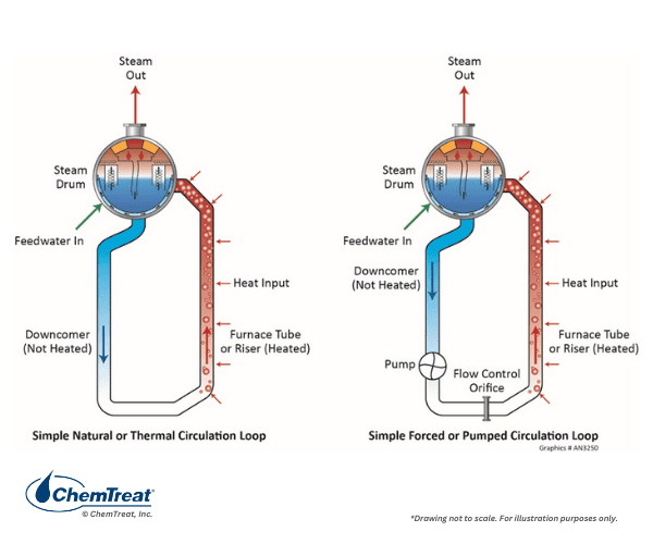
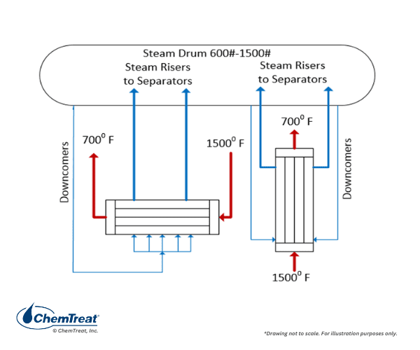
Natural or Forced Water Circulation: Boiler water circulation in drum units may be natural or forced, as Figure 4.7 illustrates. Natural circulation is often the design pattern in smaller boilers, with a typical waterwall tube diameter of 2–3 inches The difference in density between the fluid in the unheated downcomer pipes and the heated riser tubes induces flow. For large drum boilers, and particularly for many coal-fired units of the past, forced circulation was standard. It is vital in steam generators to maintain nucleate boiling, where only small steam bubbles form on tube surfaces and are then washed away by the circulating water. Problems arise if large steam bubbles form and develop into a film on boiler tubes.
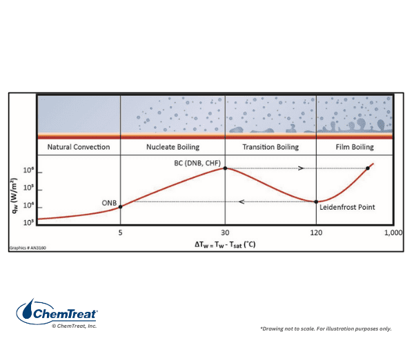
Departure from nucleate boiling (DNB) can reduce cooling such that tube overheating may occur. Forced circulation is necessary in large, high-temperature boilers to minimize non-nucleate boiling. Additionally, forced circulation allows for smaller tube diameters, and correspondingly higher pressures.
Common Industrial Boiler Designs
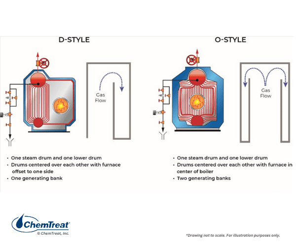
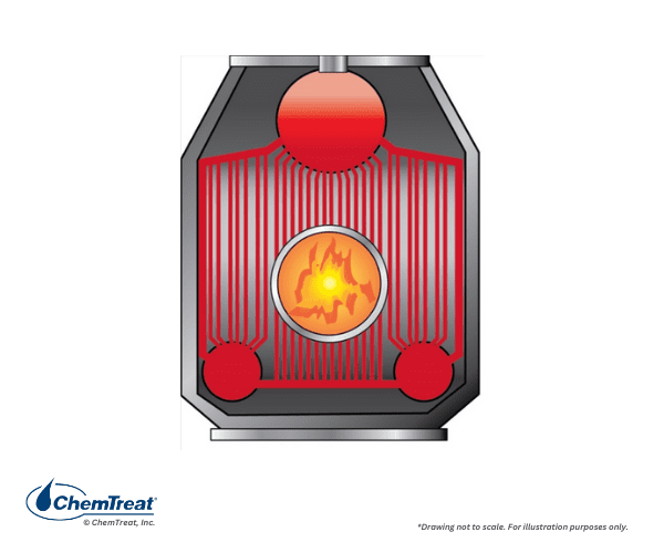
The next sections illustrate many of the most popular boiler designs. Some common industrial watertube boiler classes are D-Style and O-Style, both with a single steam and single mud drum, and A-Style with single steam and two mud drums. The following illustrations are examples of these watertube boilers.
The figure below shows a side view of a common industrial boiler, illustrating how the burners are often arranged in these units.
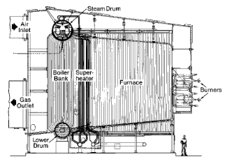
Natural gas is the most common fuel for modern industrial boilers. Some older, oil-fired boilers may still be in operation. In chemical plants or refineries, they may also burn waste fuels, often in combination with natural gas.
RETURNING CONDENSATE TO STEAM BOILERS RESULTS IN COST SAVINGS AND REDUCED CO2 EMISSIONS FOR STEEL PICKLING PLANT
Specialty Boilers
Many types of specialty boilers serve the light industry. Although some of these boilers, e.g., Clayton and Miura units, produce steam, some are just hot water generators. Key selection criteria for new boilers of any type include:
- Quantity, pressure, temperature, quality, and purity of steam required
- Flexibility in operation, particularly load variability
- Other criteria such as availability, siting, permitting, and others
Electric boilers were introduced in 1905, but not many are in service now. Their chief advantage is that steam can be generated without the fuel, ash, flue gas, and other issues of conventional units. Most are small in terms of steam pressure and generation but can range up to 450 psi with 175,000 pounds per hour of production.
When it comes to direct-fired specialty units, Clayton boilers offer lower capital cost, a small footprint, rapid response, and fuel efficiency over conventional firetube or watertube boilers in some situations. The coil-type steam generator, as shown below, is typical.
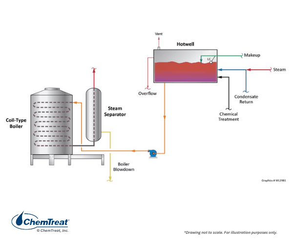
Clayton boilers have a helical coil heat exchanger to warm once-through, forced-flow water. The water moves counter current to the flow of the combustion gases, providing high fuel-to-steam efficiencies. The firing rate of the boiler regulates feedwater flow; the higher the firing rate, the higher the water flow. A mechanical steam separator removes residual moisture as the water exits the coil.
A unit of 1,000 HP (34,500 pph steam) is considered large. Steam pressures are limited to approximately 600 psi, although most units operate well below this pressure. Given the absence of a conventional steam drum and only minimal steam separation, a steam generator of this type may require additional steam/water separation equipment for high-quality (>99.5%) steam production.
Consistent softened makeup water is critical. Automatically regenerated twin softeners are strongly recommended. Hardness upsets due to faulty makeup softener operation may result in tube failures from scale formation on the heating coil. For internal boiler water treatment, precipitating programs, e.g., phosphate-based, are not recommended because of the small tube, once-through design, with its attendant water flow restrictions and high heat flux. Dissolved oxygen (D.O.) concentrations can be high in these units, which generally eliminates chelant treatment programs.
Some systems may have a Semi-Closed Condensate Receiver (SCCR), which presents potential oxygen corrosion issues that may require increased scavenger dosing during outages.
Miura offers two classes of boilers: LX gas-fired steam boilers and EX dual-fuel steam boilers. The LX series are high-efficiency boilers that operate on natural gas, propane, or both.

Depending on the model, several pressures are available, including 300 psi maximum allowable operating pressure (MAWP), 170 psi MAWP, and 15 psi MAWP. Along with the high efficiency, other advantages over firetube boilers include:
- Quick startup: units can transition from cold start to full steam in less than five minutes
- Smaller footprint: boilers have a significantly smaller footprint than conventional firetube boilers
- Low flue gas NOx emissions: some models are rated for as low as 9 ppm
The Miura EX series is designed for facilities that must have a secondary fuel source. While these boilers can operate on natural gas and propane, like the LX type, they can also be fired with #2 fuel oil. Various models in the EX series offer an array of operating pressures, including 300 psi MAWP, 250 psi MAWP, and 170 psi MAWP. As with Clayton boilers, proper makeup treatment and well-administered internal boiler water programs and maintenance practices are necessary.
A new class of boilers, such as those by Patterson-Kelley, have aluminum heat exchangers. These units generally do not produce steam but rather just hot water. Aluminum and aluminum alloy heat exchangers have certain advantages over mild steel, including:
- High thermal conductivity
- Corrosion resistance
- Lighter weight
- Smaller footprints
Typically, the manufacturers of these heat exchange devices recommend a pH range of perhaps 6.0–8.5, which is below the typical range recommended for conventional boiler and hot water systems. This can present problems if the aluminum heat exchangers are installed in systems with steel and copper alloy equipment. Operating at lower pH to protect aluminum increases the corrosion potential of the other materials. Additionally, the presence of several different metals in a system can set up sites for galvanic corrosion.
Silicates, nitrites/nitrates, azoles, and molybdenum have all been utilized for treatment of hot water boilers, often in a blend of several compounds. Phosphate is not recommended in systems containing aluminum components. As with other boilers, proper makeup treatment is necessary. Owner/operators should consult with their water treatment representative to develop an appropriate program.
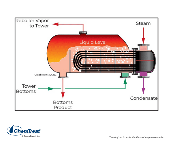
Reboilers are heat exchangers that utilize steam (or hot process fluids) to transfer energy to other process liquids or gases. A prime example is a reboiler at the bottom of a refinery distillation tower. Fundamentally, distillation columns separate fluids into fractions, with lighter fractions moving upwards and heavier fractions at the bottom. The bottoms are heated in a reboiler to recover additional lighter fractions for further processing. Steam is a common heat source for the reboiler.
A kettle reboiler is shown in Figure 4.14. Often, these units are designed for natural circulation, but some may have forced circulation. Steam reboilers face corrosion issues that may be induced by configuration, steam quality, and chemistry issues, including carbon dioxide (CO2) and dissolved oxygen ingress, and poor pH control.6
Jacketed kettles, reactors, and vat processes are utilized in food processing and chemical manufacturing. Some have direct steam contact, where the steam becomes a product component when it condenses and delivers energy. Other systems are closed, with steam flowing through a coil-type or jacketed heat exchanger and condensate returning to the boiler.
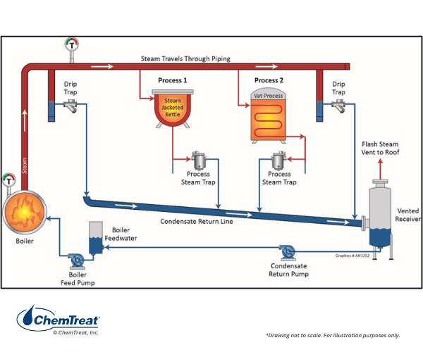
This schematic also illustrates a very important component of virtually all steam systems: steam traps. Some steam will condense within the system, and it should be collected to maintain system efficiency and reliability. The American National Standards Institute (ANSI) defines a steam trap as a “self-contained valve that automatically drains the condensate from a steam-containing enclosure while remaining tight to live steam loss.”If steam traps are not maintained properly, significant financial losses can result from excessive loss of live steam from malfunctioning traps. Conversely, condensate that is not drained properly can cause steam flow problems downstream.
Power Generation Boilers
A brief discussion of coal plant design is warranted at this point, as some of these units still operate in the United States, and some are still being built in other regions, most notably in Asia. An examination of the complete water circuit of a coal plant provides valuable information on how the various heat exchangers within the network are designed to maximize efficiency and produce steam for the intended application. Some important coal-fired heat exchanger details will then be compared and contrasted to the HRSGs of combined-cycle power plants.
Coal-Fired Plant Design
The need for rigorous understanding of coal-fired power plant design and operation continues to diminish, as in many countries these units are being phased out of operation. Two primary factors for coal’s decline are concerns related to carbon dioxide release and its influence on climate change, and the fact that alternative energy supplies such as natural gas and renewable sources have become much more viable economically. Furthermore, environmental issues involving flue gas, ash, and wastewater discharges, and corresponding pollutant control requirements for coal plants, can significantly influence the economics of plant operation. These issues are covered more extensively in Chapter 5. However, coal-fired power plants are still scattered throughout the world, and for plant managers, operators, and technical personnel at those facilities, proper monitoring and control of steam generation chemistry remains a critical issue.
Many early coal-fired boilers were of the stoker variety, where chunks of coal were loaded onto a grate, with air blown upwards through the grate for combustion. More modern designs utilize a traveling grate, in which fresh fuel is loaded at the entrance to the furnace and the grate continually moves through the combustion zone. Ash is discharged at the tail end of the traveling grate.
Stoker boilers are still in existence, and they may offer the best technology for firing alternate fuels such as municipal waste and biomass.
Most coal units that remain in the United States, and those still being erected in other parts of the world, are of the pulverized coal type, in which the coal is ground to a fine powder and ignited in burners at the furnace walls or corners. Combustion occurs very rapidly in pulverized coal units. Chapter 5 provides more information about coal properties and chemistry, and those of the ash produced from coal units.
The peak period for large coal plant construction was in the mid-20th century, with drum-type units being the most popular design. Boiler size ranged from perhaps 25 MW to near 1,000 MW. Figure 4.17 illustrates a common design from that era.
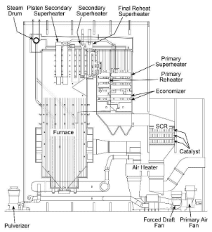
Immediately obvious is the pronounced vertical nature of the boiler as compared to industrial gas-fired boilers. The large furnace provides residence time to properly combust the solid fuel and distribute heat to the waterwall tubes. Note the series of heat exchangers that reside in the gas path downstream of the furnace, including the superheater sections, the reheat superheaters, the economizer, and the air heater. The functions of these heat exchangers will be outlined shortly.
Boiler dimensions depend not only on the desired steam production, but also the type of coal being combusted. During the heyday of large plant construction, many units were designed for the bituminous coals of Illinois, West Virginia, and other eastern locations. The combination of high heat content and sufficient volatile components that ignite quickly made bituminous coal the best option for many boilers. But the higher sulfur content of most bituminous coals induced a switch by some power plants to the low-sulfur coal from the Powder River Basin of Wyoming and Montana. PRB coal has a lower heat content than bituminous, requiring a higher fuel feed rate and larger furnace volume for equivalent steam production. Finally, some power plants were placed directly adjacent to large lignite coal deposits in North Dakota and Texas. Lignite typically has the lowest heat content of all commercial coals. The wide variability between coal chemistry and the slagging behavior of the ash produced has a large influence on furnace size. An illustration of comparative size is shown below.
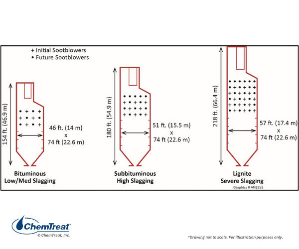
Solid fuel boilers are equipped with sootblowers (usually steam, but sometimes air-driven) to control slag formation on the furnace walls.
Additional details on coal properties may be found in Chapter 5. Meanwhile, we will turn our attention to water and steam issues related to these units. Figure 4.19 below illustrates the water/steam network of a conventional power unit.
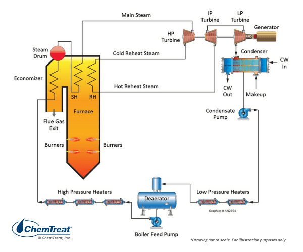
We will consider the various heat exchangers in this circuit, apart from the boiler, which are all designed to increase net efficiency and provide steam of the required pressure and temperature to the turbine.
Superheaters, Reheaters, and Feedwater Heaters
In drum units, steam exiting the drum is in a saturated state, which means that as soon as the steam does work, it begins to condense. Some industrial processes are designed for saturated steam heating, with direct condensation of the steam on tube bundles or in steam jackets, or perhaps even direct steam injection to the process. Such applications recover the steam’s latent heat and are thus thermodynamically quite efficient. But for other applications, and particularly those in which the steam drives a turbine, early condensation can be problematic. A general rule of thumb for power turbines is a moisture limit of 8 to perhaps 10% at the low-pressure turbine exhaust. Anything greater can cause serious blade erosion and damage. (Additional details on steam turbine operation are provided later in this chapter.)
Accordingly, all power steam generators and many high-pressure boilers at industrial plants are equipped with superheaters, and, usually for power units, reheat superheaters. Consider the steam-generating system outlined in Appendix 4-1, with a boiler pressure of 2,400 psi and a superheated steam temperature of 1,000°F. The saturated steam temperature is 662°F with an enthalpy (Hg) of 1025.5 Btu/lbm. The degree of superheat is therefore 338°F. The superheated steam tables indicate an enthalpy of 1,458.8 Btu/lbm at these conditions. This difference in enthalpy (433.3 Btu/lbm) provides the energy to drive the turbine. These basic calculations show that the energy transferred is only about a third of that contained in the main steam. Much of the latent heat is lost in the condenser.
Most power boilers also include a superheating reheater, or reheater for short. The reheater takes the exhaust steam from the high-pressure turbine and raises the temperature to main steam conditions, albeit at reduced pressure. For the example shown in Appendix 4-1, the reheat pressure is 546 psi, which is about one-fifth of the main steam pressure. The reheater serves two purposes. First, it improves the overall net efficiency of the unit by a few percent. Second, and even more important, is the impact of steam reheating on turbine exhaust steam conditions. In a boiler with only main steam superheating, the moisture content at the turbine exhaust may easily exceed the 8–10% guideline mentioned earlier. Steam reheating mitigates that problem. Some moisture still forms in the last few rows of the low-pressure turbine blades (which can present chemistry problems, as will be discussed), but at levels below those that would cause worrisome mechanical damage.
Note the five closed feedwater heaters and the deaerator in the condensate/feedwater circuit of Figure 4.19. The maximum number of feedwater heaters in very large units may reach eight. The primary purpose of the heaters, particularly the closed heaters, is efficiency improvement. The energy source for each heater is extraction steam from the turbine. Consider a unit without feedwater heating. For all practical purposes, the turbine utilizes only the superheat energy of the steam, with the latent heat being lost in the condenser. With feedwater heating, that portion of the steam supplied to each heater has already performed some work in the turbine. However, the remaining energy is not lost in the condenser but is directly transferred to condensate and feedwater, reducing the amount of heat input required in the boiler. Feedwater heating improves net efficiency by several percent.
The deaerator is also a feedwater heater, but its function is tied to chemistry control of the boiler feedwater and is discussed in the condensate/feedwater chemistry section later.
Another common heat exchanger in many boilers is the economizer. Per Figure 4.19 and Appendix 4-1, the economizer tube bundles are situated in the flue gas ductwork after the superheater sections. The economizer extracts additional heat from the flue gas and basically serves as another feedwater heater to improve boiler efficiency.
Also shown in Appendix 4-1 is the air heater. Like the economizer, this heat exchanger utilizes flue gas for the energy source. The two most common air heater types are the tube and rotating basket styles. The air heater offers additional efficiency improvement. Typically, a portion of the heated air is fed to coal grinders and pulverizers as a transport fluid to move the fuel to the boiler. The heated air helps remove moisture that may have entered with the solid fuel. This can be particularly important for minimizing wet-coal plugging of grinding equipment.
Supercritical Steam Generators
Thermodynamic calculations clearly show enhanced steam generator efficiency with increased operating temperature and pressure. Accordingly, of the coal-fired plants that are still being constructed in some areas of the world, many are designed for supercritical pressures above 3,200 psi. Some advanced ultra-supercritical (USC) units operate at or slightly above 4,500 psi with reheat steam temperatures near 1,200°F. At these conditions, water and steam exist as a single phase, and thus the drum design is no longer valid. A common supercritical design might have three waterwall “passes” within the furnace, where each pass is connected to the next pass by headers. Supercritical boilers usually have a start-up drum to produce steam when the boiler is being fired from cold conditions. Once the required start-up pressure and temperature are achieved in the unit, isolation valves close to remove the drum from the circuit. Supercritical units cannot tolerate feedwater contamination, as the solids would precipitate on the tube walls when feedwater converts to the single-phase fluid in the boiler. A requirement for all supercritical units is a high-purity makeup water system and a full-flow condensate polisher to capture impurities that might enter from a condenser tube leak or other source.
Combined-Cycle Power Generation
The most modern USC units have a maximum 45% net efficiency or perhaps slightly higher. Thus, even in these advanced designs, over half the energy supplied to the unit is still not recoverable. The quest for higher efficiencies, coupled with other factors related to economics and reduction of carbon dioxide emissions, led to the development and growth of combined-cycle power plants, particularly in the last decade of the 20th century and continuing into this century.
An overview of combined-cycle power generation is illustrated in the figures below.
Usually, about 2/3 of the total power from a combined-cycle plant is generated by the combustion turbine (CT). The CT resembles an aircraft jet engine and operates on the Brayton thermodynamic cycle. Many CTs without HRSGs, known as simple cycle units, are scattered around the country to serve as a rapid power supply if demand changes suddenly. But a significant amount of energy is lost in the simple cycle mode. By capturing the exhaust heat to generate steam in a Rankine thermodynamic cycle, overall plant efficiency is greatly improved. Modern combined cycle units may reach or even slightly exceed 60% net efficiency, which is much better than the best conventional steam-producing power units.
A variety of HRSG designs is available, including even some once-through types, but most are of the multi-pressure drum style. The schematic of a very common design is shown below.
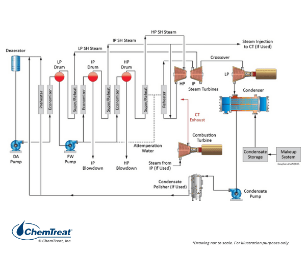
Several features of Figure 4.21 require further explanation.
- FFLP stands for feed-forward low-pressure and signifies that all incoming feedwater flows into the low-pressure (LP) evaporator. The LP circuit primarily functions as a feedwater heater, with only a small amount of steam production. The LP discharge feeds the intermediate-pressure (IP) and high-pressure (HP) evaporators.
- Because steam attemperation water is taken from the feedwater (FW) pump with the LP evaporator as the source, no solid alkalis, e.g., tri-sodium phosphate or caustic, can be utilized for pH control in the LP evaporator. Rather, the ammonia, or perhaps an ammonia/amine blend, injected to the condensate provides pH control in the LP evaporator.
- The diagram shows a deaerator bypass line, but in some modern designs, a deaerator may not even be included. This comes from chemistry developments designed to minimize flow-accelerated corrosion (FAC) in the LP evaporator and economizers. (A later section discusses FAC, which affects many types of steam generators, particularly power units.)
- During normal operation, the energy for steam production comes from the combustion turbine exhaust. However, many HRSGs are equipped with supplementary duct burners to increase steam generation capacity during times of peak loads.
As Figure 4.21 suggests, the tubes in this design have a vertical flow pattern but with the sections arranged horizontally through the gas path. Finned tubes are common to increase heat transfer.
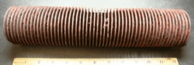
Even though virtually all combustion turbines are fired with natural gas, the finned tubes can still accumulate dust particles that inhibit heat transfer. Also, because of the close spacing of the various tube bundles within the unit, if tubes fail from poor chemistry or other operational practices, repair and replacement can be quite difficult and time-consuming. Proper water chemistry control is also important to minimize chemical cleanings of HRSGs. Chemical cleanings are never easy, even in conventional units, but for multi-pressure HRSGs the process can be especially complicated.
Waste Heat Steam Generators for Chemical Manufacturing and Refining
Specialized steam generators exist at many plants to recover process heat. Applications include:
- Heat generated as a necessary part of the process, which would otherwise be discarded. Examples include syngas processes such as ammonia, methanol, and hydrogen.
- Heat that is a byproduct of a chemical manufacturing process, such as black liquor boilers in paper manufacturing and ethylene cracking quench boilers that cool the cracked hydrocarbons.
- Heat available from combustion of residues such as waste wood, agricultural waste, garbage, and carbon monoxide (CO) gas generated from crude oil cracking in a refinery or blast furnace gas in a steel mill.
Many processes produce gases with temperatures greater than 1,000°F. The waste heat boilers can operate as firetube or watertube boilers depending on the process.
| Gas Source | °F | °C |
|---|---|---|
| Syngas Ammonia Reforming | 1,350–1,475 | 730–800 |
| Ethylene Cracking Furnace Quench | 1,380–1,607 | 750–875 |
| Annealing Furnaces | 1,100–2,000 | 590–1,090 |
| Black Liquor Recovery Furnace | 1,800–2,000 | 980–1,090 |
| Cement Kiln (dry) | 1,150–1,350 | 620–7,30 |
| Coke Oven (beehive) | 1,900–2,300 | 1070–1,260 |
| Forge and Billet Heating | 1,700–2,200 | 930–1,200 |
| Garbage Incinerator | 1,550–2,000 | 840–1,090 |
| Open Hearth Steel furnace | 1,200–1,300 | 650–700 |
| Petroleum Refining Still | 1,000–1,100 | 540–590 |
| Sulfur Ore Processing | 1,600–1,900 | 870–1,040 |
Space limitations prevent a detailed discussion of the various boilers that generate steam from these processes, but a very illustrative example comes from the ethylene industry, where primary unit operation comes from a cracking furnace. The hot, cracked gas must be quickly cooled to minimize additional cracking. Cracker gas cooling takes place in steam generators known as Trans Line Exchangers (TLE or TLX). The hot gas flows through the tube side of the boiler with water on external tube surfaces. The exchangers may be oriented horizontally or vertically with high-pressure steam produced in a steam drum that connects TLEs. Gas temperatures may be at or near 1,500°F, with produced steam pressures up to 1,800 psi.
Careful observation reveals that the configuration to some extent resembles a firetube boiler, with the hot gases flowing through the tubes and steam being generated within the shell.
Not uncommon with non-traditional boiler designs is the potential for localized high-heat spots that can accentuate deposition and corrosion. Consistent high-purity makeup water production and carefully designed boiler water treatment programs are key components for reliable performance.
How to Minimize Corrosion & Deposition in High-Purity, High-Pressure Steam Generators
Steam Generation Chemistry
Makeup, condensate, and boiler water treatment and chemistry requirements vary significantly depending on such factors as boiler pressure and configuration, heat input method (direct or waste-heat fired), steam function (energy for process heat exchangers or to drive turbines), and so forth. A good illustration of the general chemistry requirements for industrial boilers is as follows:
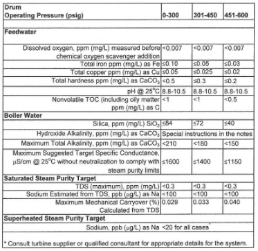
This data was extracted from Table 1 in Reference 8 [ASME] and represents just a partial view of the entire table. The booklet contains many additional details regarding industrial boiler water guidelines.
As this extract indicates, the limits become tighter as boiler pressure increases. Appendix 4-2 outlines impurity limits for high-pressure utility units.
Makeup Water Treatment
Makeup treatment methods for a variety of plant applications from cooling water to high-purity needs are covered in Chapter 3. This section provides a brief overview of makeup requirements as they relate to boiler pressure in general.
Basic sodium softening is very common for low-pressure boiler makeup. Since humans began heating water for cooking or sanitary purposes, they have undoubtedly observed mineral deposition in heated vessels. The primary culprit is calcium carbonate.
Ca2+ + 2HCO3– + heat → CaCO3↓ + CO2 + H2O | Eq. 4-1
The equation outlines the reaction of calcium ions (Ca2+) and bicarbonate alkalinity (HCO3–) that often occurs in hot water systems and boilers.
Accordingly, sodium softening became and remains a common makeup treatment process for many industrial steam generators. Raw water passes through a bed of ion exchange resin, whose active sites contain sodium ions. These sites have a stronger affinity for calcium and magnesium than sodium, and thus the hardness ions are exchanged for sodium as the water flows through the bed. When the bed reaches exhaustion, it is regenerated with a brine (NaCl) solution that drives off the hardness ions into a waste stream that is discarded. The softened stream, with hardness removed, still contains the other dissolved ions, including alkalinity, chloride (Cl–), sulfate (SO42-), and silica (SiO2).
As Figure 4.24 suggests, low-pressure boilers can tolerate some impurities, including alkalinity. Indeed, for some applications, alkalinity may be desirable as it helps protect metal surfaces from corrosion. However, HCO3–, upon reaching the boiler, is in large measure converted to CO2 via the following reactions:
2HCO3– + heat → CO32- + CO2↑ + H2O | Eq. 4-2
CO32- + heat → CO2↑ + OH– | Eq. 4-3
The total conversion of CO2 from the combined reactions may reach 90%. CO2 flashes off with the steam and when it re-dissolves in the condensate, can increase the acidity of the condensate return.
CO2 + H2O ⇌ H2CO3 ⇌ H+ + HCO3– | Eq. 4-4
Although the pH generated by this reaction has a relatively mild lower limit, the acidity is more than enough to cause significant carbon steel corrosion in condensate return systems. For example, 3 ppm of CO2 in pure steam condensate will lower the pH to 5.26. If dissolved oxygen is present in the system, corrosion can be magnified.
Accordingly, many sodium softening systems are often followed by a split-stream dealkalizer or a decarbonator to reduce alkalinity to low ppm levels. The fundamental chemistry in either process acidifies alkalinity to convert it to carbon dioxide, which is then extracted as a gas from the treatment system.
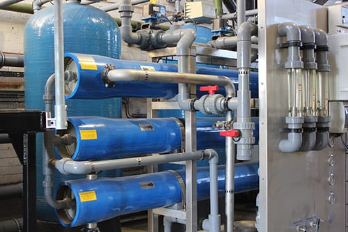
Makeup Water Treatment for High-Pressure Steam Generators
For high-pressure utility units, the feedwater must be very pure to minimize corrosion and other potential problems in the steam generator. Impurity concentrations are normally limited to low ppb ranges. Well-known guidelines for makeup system effluent purity are:
- Specific conductivity: ≤0.1 µS/cm
- Sodium: ≤2 parts-per-billion (ppb)
- Silica: ≤10 ppb
Ion exchange demineralization was commonly used throughout the last century to achieve this purity. Of the various ion exchange combinations possible, the most popular was the following configuration:
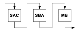
SAC = Strong acid cation exchanger
SBA = Strong base anion exchanger
MB = Mixed bed exchanger
This ion exchange configuration, and some variations of it, can be very effective at producing high-purity water. However, one critical factor has led to a variant of this technology for makeup treatment in high-pressure and some intermediate-pressure steam generators. The issue is that most raw waters have several hundred mg/L of combined cations and anions. When introduced directly to ion exchange systems, the resins may exhaust within a relatively short period of time, sometimes within hours. A typical arrangement has two identical systems. When one exhausts, the other is placed in service, with the SAC and SBA resins in the exhausted system being regenerated with a strong acid and strong base, respectively. However, frequent regenerations are somewhat expensive and require plant personnel to work with dangerous chemicals on a regular basis. Reverse osmosis (RO) technology has become very common for bulk removal of dissolved ions. It supplants the SAC and SBA ion exchange vessels shown in Figure 4.27 and can often serve as the stand-alone demineralization process for intermediate-pressure boilers. Reverse osmosis details are also covered extensively in Chapter 3.
In the power industry, two-pass RO has in many cases replaced SAC and SBA exchangers. Final treatment is then performed with portable mixed-bed (MB) technology, wherein a contractor supplies MB “bottles” that have simple connections to the system. When a bottle becomes exhausted, plant personnel switch to a redundant system, and the contractor removes the exhausted bottle for resin regeneration off-site. An alternative polishing method is continuous electrodeionization (CEDI), which utilizes both membrane and ion exchange technology to produce the required high-purity makeup. The resin in these systems is automatically regenerated and thus can operate for long periods without maintenance.
One form of makeup water production that deserves a brief mention is evaporation. Raw water is evaporated with waste heat and is then condensed as product. Evaporators were common in older, subcritical utility plants and remain in wide use for marine steam generators.
KEYS TO RELIABLE MAKEUP WATER TREATMENT FOR BOILERS
Condensate/Feedwater Chemistry
While several general principles apply to condensate/feedwater treatment and chemistry control for all steam generators, variabilities in system design influence specific programs. Steam generators for power production can be thought of as nearly closed systems with the makeup system easily supplying water and steam from small losses. Impurity ingress is often nil unless it comes from a leak in a steam surface condenser (or occasionally a makeup system upset). Accordingly, the primary feedwater treatment goals for these systems involve minimizing both general corrosion and FAC of carbon steel condensate/feedwater piping, deaerators, economizers, and, for multi-pressure HRSGs, the low-pressure evaporator. FAC control requires a different mindset regarding feedwater dissolved oxygen (D.O.) concentrations, as will be outlined.
At the opposite end of the spectrum are industrial facilities in which steam provides energy to multiple heat exchangers and is then recovered as condensate for return to the boiler. Depending on the processes that utilize steam heating, a wide variety of contaminants are possible in the condensate return. These may range from mineral salts to organic compounds to particulates generated from corrosion of condensate return piping.
The following sections focus on two issues, the influence of pH and D.O. on feedwater system corrosion. The discussion includes current state-of-the-art methods for feedwater treatment.
Dissolved Oxygen
Oxygen corrosion of iron and mild steel is a phenomenon that has been observed for centuries. Rusting of outdoor structures is a classic example.
Early on, boiler chemists and engineers developed methods to minimize air ingress to steam generators and remove dissolved oxygen in the condensate. During normal operation, oxygen can enter the steam-generating system from several sources. One is atmospherically-vented condensate storage tanks. When a unit needs makeup, the water from one of these tanks may contain up to 10 ppm of D.O. A common system design to extract much of the D.O. introduces the makeup to the condenser so the strong vacuum will cause oxygen to escape per Henry’s Law, which states that the equilibrium concentration of a gas dissolved in liquids is proportional to the partial pressure of the gas above the liquid.
However, a pathway for oxygen ingress also exists at the condenser. When turbine exhaust steam is cooled in the condenser, the dramatic collapse in volume from vapor to liquid induces a strong vacuum within the condenser shell. Outside air will be pulled in at even the smallest openings and at spots in piping connections to the condenser. Accordingly, most condensers are equipped with an air-removal system to prevent gases from accumulating, as air can coat condenser tubes and cause serious heat transfer degradation. Some oxygen will remain, however, and will partially dissolve in the condensate. Air may also enter condensate on the suction side of condensate discharge and feedwater pumps. In large industrial plants, air may also infiltrate at numerous places around heat exchangers and in the condensate return system.
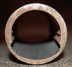
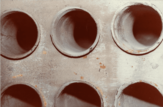
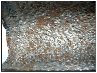
As steam generation technology evolved for power production and industrial processes, the influence of oxygen on corrosion of piping, heat exchanger tubes, and other components quickly became evident. Frequently, oxygen attack is localized, with deep pits forming at sites of active corrosion. This type of corrosion is very damaging and can cause the failure of economizers, deaerator equipment, condensate piping, condensate receivers, and other equipment.
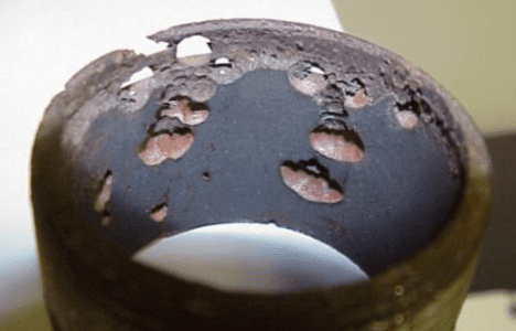
For many years, it was thought that all dissolved oxygen must be removed from feedwater to minimize the corrosion shown in Figure 4.28 and protect any copper alloys (most commonly feedwater heater tubes) in the system. Accordingly, almost all steam-generating systems were equipped with a mechanical deaerator.
The two common styles of deaerator are spray-type and tray-type, with the latter being more popular.
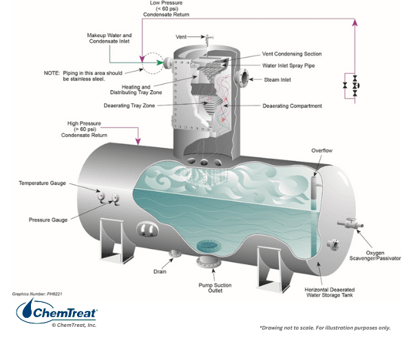
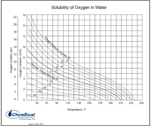
The solubility of oxygen in water greatly diminishes with rising temperature, as outlined in the chart below.
Influent condensate to the deaerator discharges through spray nozzles and cascades over staggered sets of trays, with steam introduced from below the trays.
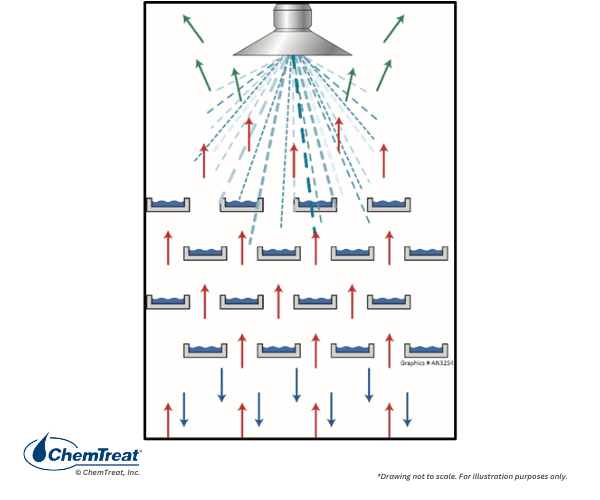
Non-condensable gases, primarily oxygen, are released and escape through the deaerator vent along with a small amount of steam. The condensate is heated to within a few degrees of saturation temperature and discharges to the deaerator storage section.
The high surface area of the trays allows for rapid oxygen removal. The typical design guarantee for tray-type deaerators is 7 ppb effluent D.O. An increase in D.O. concentration in the deaerator outlet sample indicates a problem within the deaerator compartment. Common issues include:
- Misaligned or missing trays
- Damaged or malfunctioning spray nozzles
- Restricted steam admission
- Incorrect settings of deaerator vents
Feedwater storage sections should be large enough to hold at least 15–20 minutes of feedwater at maximum steam production.
Some small steam generating systems may have very simple deaeration methods, such as a steam sparger on the bottom of the storage drum. Oxygen removal correlates to the temperature that can be achieved in the vessel.
Oxygen Scavengers/Reducing Agents/Metal Passivators
Even though a well-designed and operated mechanical deaerator can reduce DO concentrations to approximately 7 ppb, in the past, this level was still considered to be excessive. So, at many plants, chemical treatment supplemented mechanical deaeration. These chemicals are oxygen scavengers/reducing agents, many of which are also metal passivators. The most common are:
- Sulfite (catalyzed and uncatalyzed)
- Erythorbate (also referred to as erythorbic acid [EA])
- Hydrazine
- Diethylhydroxylamine (DEHA)
- Carbohydrazide (CZ)
- Methylethylketoxime (MEKO)
- Hydroquinone (HQ)
The list is ordered generally by the amount of product consumed per year, excluding hydrazine, as will be explained. A common compound is sodium sulfite (Na2SO3), as it is suitable for many boilers up to approximately 600 psig in pressure.
2Na2SO3 + O2 → 2NaSO4 | Eq. 4-5
A typical injection point is the deaerator storage tank. Sulfite reacts over a wide range of temperatures, although, as with all scavengers, reaction rates increase with increasing temperature. Reaction time is important. A poorly operating deaerator (especially with a small storage section) can allow serious oxygen attack in feedwater piping and economizers because the scavenging reactions are not completed before the feedwater reaches the boiler. Sulfite often includes a cobalt catalyst to speed reactions, although some research suggests the catalyst may not be altogether effective.
Typically, sulfite is measured as a residual in the boiler water even though it is often injected in the feedwater system. A once-common range was 30–60 ppm in low-pressure boilers, with decreasing levels at higher boiler pressures. Being non-volatile, sulfite remains in the boiler water and does not escape with steam. Sulfite (and erythorbate, outlined below) should not be utilized in steam generators that provide attemperating water to steam, as this will lead to direct introduction of non-volatile solids to steam systems and, most critically, turbines. Another issue is sulfite decomposition. Some literature suggests that sulfite may be employed at pressures up to 900 psi, but at the high temperatures in such boilers, sulfite will break down to produce hydrogen sulfide (H2S) and acid. These products can cause significant damage to boiler metal. A more practical upper limit for sulfite use is 600 psi. Sodium sulfite is often selected as a layup chemical for low-pressure boilers, but the solution should not be allowed to enter superheaters, especially if they are non-drainable.
Erythorbate/erythorbic acid (or the typical feed material, sodium erythorbate, C6H7NaO6) is a non-volatile, FDA-approved alternative to sulfite. The reaction with oxygen is complex, but reaction rates are rapid. Erythorbate is an excellent passivator for low- and medium-pressure boilers. Before proceeding, the reader is encouraged to review Appendix 4-2, which discusses metal passivation and the role of these chemicals in that process.
For high-pressure boilers and, most notably, power units, hydrazine (N2H4) was once the primary feedwater reducing/passivating agent. The breakdown products of residual hydrazine are ammonia and water, so neither the hydrazine nor its decomposition products introduce non-volatile solids to the feedwater or steam. Thus, the chemical was ideal for treatment ahead of any steam attemperator take-offs. However, hydrazine is now rarely used as it is considered a carcinogen. Alternative chemistries are available and are outlined next.
Carbohydrazide (CH6N4O) was developed as a direct replacement for hydrazine. At elevated temperatures in the feedwater system, it converts to hydrazine. Because of the carbon component, carbohydrazide decomposition products include CO2 along with the ammonia that comes from the breakdown of the intermediate hydrazine product.
DEHA (diethylhdroxylamine, (C2H5)2NOH)) is a volatile scavenger with both neutralizing amine and passivation properties. DEHA and the others listed below serve as alternatives to hydrazine. DEHA is stable in boilers up to 1,200 psi pressure and thus offers protection to the steam condensate system as well as feedwater and boiler drums. Its initial breakdown products are diethylamine and ethylmethylamine, both also neutralizing amines. Continued thermal decomposition will yield nitrogen, water, and small amounts of acetic acid.
MEKO (methylethylketomime, C4H9NO) is a reducing agent that breaks down into ammonia and organic acid byproducts at 1,250 psi, so is not widely utilized as a hydrazine alternative in the power industry but finds use in industrial, commercial, and institutional steam cycles.
Hydroquinone (C6H6O2) is a powerful oxygen scavenger, but it is toxic and must be handled very carefully. It acts rapidly and is sometimes included with other hydrazine alternatives as a catalyst to speed reactions with oxygen. The primary decomposition product is CO2.
As will be outlined shortly, oxygen scavengers are no longer recommended due to their influence on FAC for most power steam generating systems.
Feedwater pH Control
The other primary issue regarding feedwater corrosion control is pH, or more precisely, maintenance of a moderately basic feedwater chemistry. We will begin this discussion by examining pH control in high-pressure power units, followed by an examination of industrial steam generators where less rigorous makeup water treatment and often large condensate return have a greater influence.
In the power industry, the standard method for feedwater pH control has been ammonia (NH3) feed.
NH3 + H2O ⇌ NH4+ + OH– | Eq. 4-6
The following table outlines the ammonia concentrations that correlate to the range of pH values common in feedwater systems.
| pH | Ammonia (ppm) |
|---|---|
| 9.0 | 0.274 |
| 9.2 | 0.527 |
| 9.4 | 1.070 |
| 9.6 | 2.286 |
| 9.8 | 5.105 |
| 10.0 | 11.812 |
Source: Reference 5
The influence of pH on carbon steel corrosion is illustrated in a well-known graph from the 1970s.
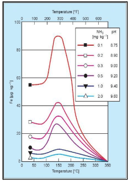
It is clearly evident that the corrosion rate decreases with increasing pH, but this, in turn, can have a strong impact on ammonia feed requirements. For example, the recommended feedwater pH25C range for the most common type of HRSG is 9.6–10.0. This requires a healthy concentration of ammonia, per Table 4-2.
In power units, a common ammonia injection point was once the deaerator storage tank or the boiler feed pump suction. However, the realization that the entire condensate/feedwater system benefits from precise pH control made feeding at the condensate pump discharge a popular choice.
In conventional high-pressure units, much of the ammonia stays in the boiler water, with only a fraction carrying over with steam. However, in multi-pressure HRSGs, most of the ammonia in the feedwater entering the low-pressure evaporator partitions with the steam and returns to the condensate. This phenomenon can influence several chemistry issues, including flow-accelerated corrosion, as will be discussed in a later section.
Industrial Condensate Return pH Control
Chemistry control of complex industrial condensate return systems can be a challenge. A common issue is pH depression from carbon dioxide carryover in the steam.
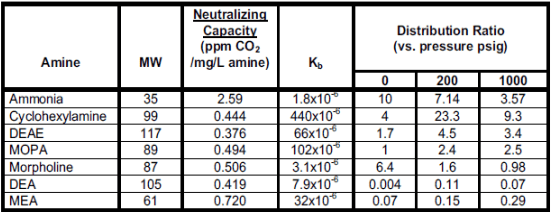
Accordingly, alkalizing amine injection to condensate systems is frequently employed to minimize corrosion in carbon steel piping. The chemical or chemical blend not only protects the condensate but carries through the system. The figure below lists several of the most common alkalizing amines.
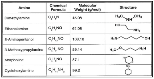
The three key aspects of amines can be summarized as the three “Ds.”
- Dissociation: Dissociation is the base strength defined by the dissociation constant kb. For the ammonia reaction shown in Equation 4-6 earlier, kb is:
kb = [NH4+] * [OH–] / [NH3]
This equation is similar for alkalizing amines. Higher Kb values (see Table 4-3 below) indicate higher basicity of the products. Basicity is variable with temperature, so this aspect must be considered when designing chemical programs.
- Distribution: Distribution is the ratio of the amine that remains in boiler water and that which enters steam. Depending on steam generation design, an amine blend can be formulated to establish desired ratios. The distribution ratio varies with temperature.
- Decomposition: Alkalizing amines decompose at high temperatures. The decomposition becomes particularly noticeable in high-pressure applications such as utility boilers. A common decomposition product is acetic acid, a small-chain organic acid. Debate has circulated for many years about whether acetate and an even smaller organic compound, formic acid, initiate corrosion on turbine blades. Evidence suggests that such corrosion is not a major concern, but the presence of acetic and formic acids in condensate influences conductivity readings. The decomposition process can establish a “Catch 22” situation, where the breakdown products lower condensate pH, which results in increased alkalizing amine feed that in turn generates more acid.
Careful evaluation of steam-generating and condensate return system operating and design conditions is necessary when selecting the most appropriate amine or amine blend. One important consideration is the presence of copper alloys in the network. Such alloys were a common choice for heat exchanger tubes due to excellent heat transfer properties, but the presence of ammonia and oxygen can cause serious copper corrosion. Other considerations center on the efficacy of some of the compounds. For example, once commonly utilized morpholine has lost favor because the relatively high molecular weight and weaker basicity (vs. the other amines) influences cost-effectiveness.
Amine feed directly to steam headers is usually the best approach from a technical standpoint; however, feed to these locations requires installation and maintenance of high-pressure pumps and injection quills. A common alternate injection point is the boiler feedwater system, although a drawback is that some of the fresh chemicals, particularly those with lower volatilities, are lost in the boiler blowdown.
The combination of ammonia or neutralizing amine feed along with a volatile oxygen scavenger/reducing agent is known as all-volatile treatment reducing (AVT(R)).
Flow-Accelerated Corrosion
For many years, a near universal mindset was that even the slightest trace of dissolved oxygen in the feedwater of steam-generating units was harmful. This assumption was especially true in the power industry. When carbon steel pipes, tubes, and other steam-generating equipment are placed in service, the metal surfaces develop an oxide layer, whose general chemistry is shown by the fundamental Schikorr reactions.
Fe + 2H2O → Fe(OH)2 + H2
3Fe(OH)2 → Fe3O4 + 2H2O + H2↑
Fe3O4 is the familiar oxide layer, magnetite, which is gray-black in color.
The magnetite layer protects the underlying steel from corrosion; however, oxygen in the feedwater will convert the magnetite to non-protective rust (Fe2O3). While many consider the reducing agents outlined above primarily as oxygen scavengers, a main function is to convert Fe2O3 to passive Fe3O4. Thus the name metal passivators. For those steam-generating systems that still have copper alloys in the feedwater network, these metals form an initial protective layer of cuprous oxide (Cu2O). Dissolved oxygen will convert this layer to cupric oxide (CuO), which is not protective. The reducing agents also convert oxidized copper back to a passive state. As will shortly be explained, in the power industry, the presence or absence of copper in the condensate/feedwater system significantly influences the choice of feedwater treatment program.
The foundations of AVT(R) chemistry received a severe jolt in 1986, for “On December 9 of that year, an elbow in the condensate system ruptured at the Surry Nuclear Power Station [near Williamsburg, Virginia.] The failure caused four fatalities and tens of millions of dollars in repair costs and lost revenues.” Researchers learned from that accident, and others since, that the reducing environment produced by oxygen scavengers is the primary ingredient for single-phase FAC of carbon steel. The attack occurs at flow disturbances such as elbows in feedwater piping and economizers, feedwater heater drains, locations downstream of valves and reducing fittings, attemperator piping; and, most notably for combined-cycle HRSGs, in low-pressure evaporators, where the waterwall tubes, aka harps, have many short-radius elbows. In fact, FAC is typically the leading corrosion mechanism in HRSGs. Note that these locations correspond to the temperature influence shown in Figure 4.32.
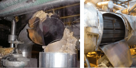
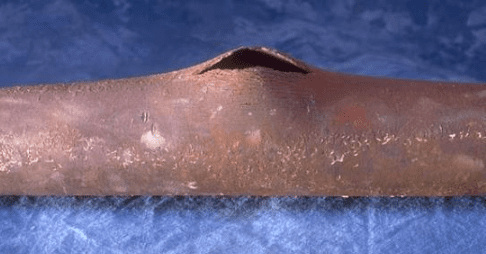
Gradual metal loss occurs at FAC locations, as illustrated in the figure below.
The reducing environment accentuates metal dissolution. Wall thinning progresses until the remaining material at the affected location can no longer withstand the process pressure, with sudden failure as the end result.
The move away from AVT(R) feedwater treatment for power units began in Europe and Russia in the late 1960s and early 1970s. Researchers and chemists at supercritical power plants discovered that in high-purity feedwater (cation conductivity ≤0.15 μS/cm), the deliberate injection of a small amount of oxygen (to establish a D.O. concentration of 50–300 ppb), and elimination of oxygen scavenger feed would cause the magnetite layer on carbon steel surfaces to become interspersed and overlaid with a different oxide layer, known variously as α-hematite and ferric oxide hydrate. With rigorously maintained chemistry, this oxide forms a much tighter bond than magnetite and greatly minimizes FAC. The program, and variations thereof, gained the name of oxygenated treatment (OT) and was adopted as the replacement for AVT(R) at many supercritical units around the world, although it is unacceptable for units with copper-alloy tubed feedwater heaters, as the combination of oxygen and ammonia will cause severe copper alloy corrosion.
Subsequently, EPRI developed a program to replace AVT(R) for drum units with AVT(O), which stands for all-volatile treatment oxidizing. If the condensate/feedwater system contains no copper alloys (which is true for virtually all modern HRSGs), then AVT(R) is not recommended. In brief, with AVT(O) chemistry, as with OT, the oxygen scavenger feed is eliminated. A small residual concentration (5–30 parts-per-billion [ppb] of dissolved oxygen) is required at the economizer inlet. Ammonia or an ammonia/neutralizing amine blend is still utilized for pH control. High-purity condensate (cation conductivity ≤0.2 µS/cm) is a requirement for AVT(O), but when proper conditions are established, the magnetite becomes overlaid and interspersed with the tighter-bonding α-hematite. The layer is noticeable for its distinct red color.

OT and AVT(O) have proven so successful that research organizations such as EPRI and others strongly recommend eliminating oxygen scavengers in all power steam generators unless the feedwater system contains copper alloys.
Some steam-generating equipment, including deaerators, and, most notably, FFLP HRSG low-pressure evaporators, have suffered from two-phase FAC. The problem arises in these vessels, especially FFLP HRSGs, because the ammonia that enters the low-pressure evaporator flashes off with steam. This leaves rapidly circulating droplets with a lower pH in the upper section of the drum, which induces corrosion, hence the name two-phase FAC. A method that has emerged to counteract two-phase FAC is blending an alkalizing amine with the ammonia feed, where the amine remains behind to maintain an elevated pH of the water droplets. A 90/10 blend of ammonia and ethanolamine is popular. Even this ratio will induce a slight rise in steam and condensate cation conductivity from amine decomposition. This effect has sometimes caused difficulties with commissioning new units, where the turbine manufacturer insists on a cation conductivity ≤0.2 µS/cm.
Film-Filming Products
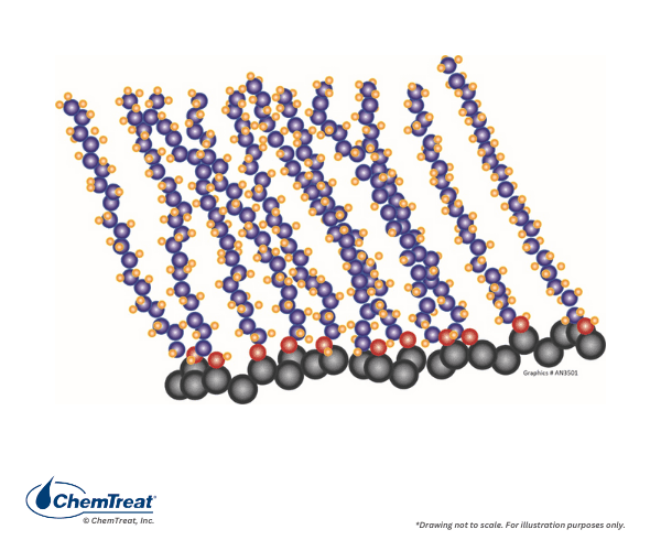
It has long been recognized that some compounds can form a protective barrier on metal surfaces and potentially minimize corrosion. Decades ago, filming amine chemistry was attempted in steam generators, with a common compound being octadecylamine (C18H39N, ODA). The amine group attaches to the metal surface, and the hydrophobic organic “tail” extends into the fluid to shield the metal.
However, poor control and lack of detailed knowledge often led to problems with ODA applications, including the formation of “gelatinous spheroids,” or “gunk balls,” in the common vernacular, which fouled steam generators.
More advanced amine and non-amine film-forming substances (FFS) have been developed. Most of these products operate best in mildly basic conditions so, ammonia or alkalizing amine feed is still required. However, FFS feed is not tied to pH or CO2 control; rather, product concentration is based on the residual concentration that best protects metal surfaces. Regular iron monitoring can be very important in evaluating and fine-tuning programs. Some products will actually cause partial dissolution of iron oxides during initial application, which can sometimes be falsely assumed to be major corrosion.
FILM-FORMING AMINES: INNOVATIVE BOILER TREATMENT TECHNOLOGY FOR THE REFINING INDUSTRY
Internal Boiler Water Treatment
As steam boilers became common for industrial power and heating applications and railroad locomotion in the 1800s, boiler explosions from overheating were regular occurrences. Evidence clearly indicated that boilers operating with softened makeup water had fewer failures and required less frequent cleanings. However, it was also apparent that internal boiler water treatment was required, especially as boiler pressures and size increased, particularly in the power industry.
During this evolutionary phase of makeup water improvements, a variety of deposition occurred, depending on the impurities present. These compounds included:
- Calcium carbonate (CaCO3)
- Calcium sulfate (CaSO4)
- Magnesium hydroxide [Mg(OH)2]
- Magnesium silicate (MgSiO3)
- Magnesium phosphate [Mg3(PO4)2],
- Silica (quartz SiO2)
- Metal oxides, most notably iron, but also copper and, at times, aluminum
- Sodium salts, including chloride and sulfate
- Carbonaceous compounds
Two of the most common scale-forming reactions are shown below.
Ca2+ + 2HCO3– → CaCO3↓ + CO2 + H2O | Eq. 4-7
Mg2+ (or Ca2+) + SiO3-2 → CaSiO3↓ (or MgSiO3↓) | Eq. 4-8
These reactions continue to plague steam generators in modern times, especially where makeup water treatment systems malfunction or other contamination occurs.
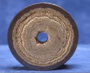
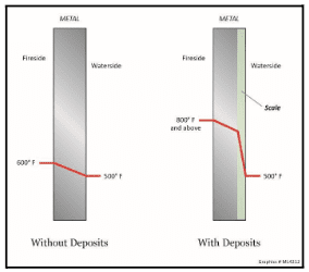
Deposition reduces heat transfer, which in turn requires increased fuel firing to produce the necessary steam. More importantly, deposits can cause overheating of tubes and subsequent failure. Figure 4.41 illustrates the effects of scale formation on tube wall temperatures.
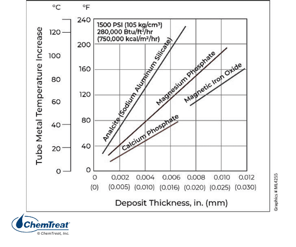
The composition of scale influences the insulating properties, as illustrated in the figure below.
Elevated tube temperatures can also induce “creep,” where the metal grains exposed to long-term high temperatures begin to slip over time, resulting in irregularities within the metal structure. Metal composition, wall thickness, and other properties are designed for the projected life of the unit. But overheating caused by scale formation or other causes can accelerate creep, shortening the life of the metal. Further exacerbating this issue is that deposition is usually greater on the hot side of the tubes. Heavy deposition from a severe upset can induce short-term overheating and rapid failure.
Appendix 4-3 outlines the maximum operating temperatures of common boiler tube steels and provides the composition of several of these materials along with brief descriptions of alloying benefits.
Early treatment methods to combat scale formation included dumping potato peels or sawdust in the boiler, as some of the organic compounds, i.e., tannins and lignins, in these natural materials sequester hardness ions. More scientific treatment methods have evolved and will be explored later in this chapter.
Mechanical factors that can influence creep and other metal properties include:
- Operating the boiler above normal maximum capacity.
- Excessive ramp rates when increasing boiler load.
- Excessive heat input in localized areas. Misaligned burners are a primary cause.
- Unbalanced or restricted flow in some tubes.
pH Control
The other primary issue, then and now, is maintaining a basic pH in the boiler water. Iron is an amphoteric metal, meaning that corrosion rates increase at both low and high pH.
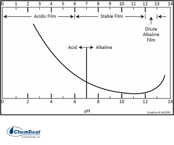
In the 1930s, tri-sodium phosphate (Na3PO4) boiler water treatment evolved to generate alkaline conditions and minimize general corrosion per the figure above.
Na3PO4 + H2O ⇌ Na2HPO4 + NaOH | Eq. 4-9
We will return to this chemistry shortly. The second major function of phosphate is to mitigate the effects of contaminant in-leakage, which, in the early days (and sometimes even now, especially in industrial steam generators), often came from poor makeup water treatment that allowed hardness to enter the boiler and form the tenacious deposits represented in Equations 4-7 and 4-8. Phosphate reacts directly with calcium to produce calcium hydroxyapatite:
10Ca+2 + 6PO4-3 + 2OH– → 3Ca3(PO4)2•Ca(OH)2↓ | Eq. 4-10
Magnesium and silica react with the hydroxide alkalinity produced by phosphate to form the non-adherent sludge serpentine:
3Mg+2 + 2SiO3– + 2OH– → 3MgO•2SiO2•2H2O↓ | Eq. 4-11
Calcium hydroxyapatite and serpentine are much easier to remove than the hard scale that would otherwise form. These sludges typically settle in the mud drum or lower headers from which they are extracted by blowdown.
In early low-pressure boilers, a common phosphate concentration range was 20–40 ppm. However, as technology advanced and boiler pressures increased, caustic gouging and embrittlement became problematic.
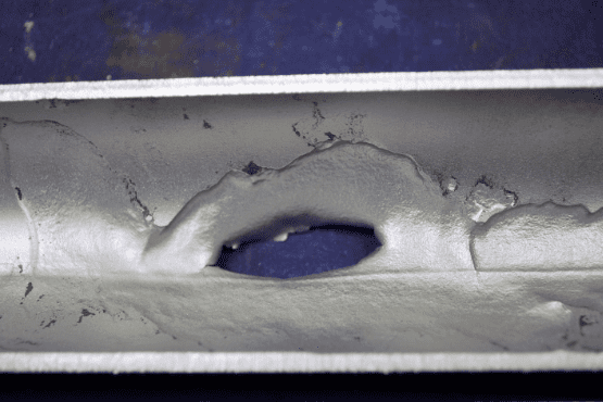
These failures typically occur underneath boiler tube deposits.
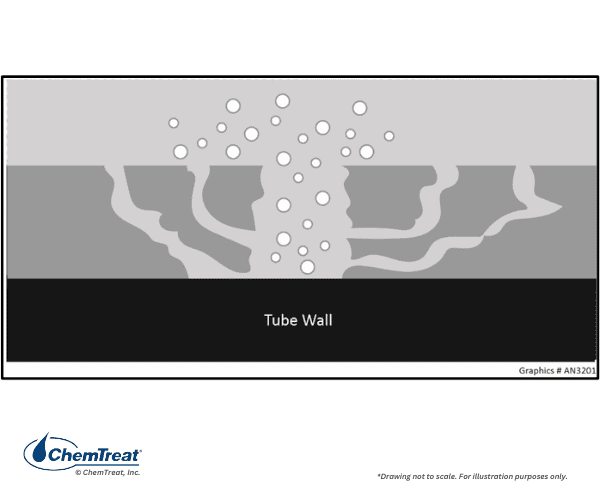
Water penetrates the deposit through various channels. As the water approaches the tube surface, temperatures increase. The water boils off, leaving other species behind. This phenomenon is known as wick boiling. Sodium hydroxide is one species that may remain, and concentrations can rise to levels many times that in the bulk boiler water. The concentrated NaOH attacks the boiler metal and protective magnetite film via the following reactions:
Fe + 2NaOH → Na2FeO2 + H2↑ | Eq. 4-12
Fe3O4 + 4NaOH → 2NaFeO2 + Na2FeO2 + 2H2O | Eq. 4-13
So, for high-pressure boilers particularly, “improved” water treatment programs emerged to bring order to corrosion and deposition control. Unfortunately, some of the modifications were less than ideal, as we shall see.
The Evolution of Power Boiler Water Treatment
This section focuses on the evolution of water treatment for high-pressure boilers (>900 psi) used for power generation. To a large extent, power boiler chemistry, after a few twists and turns, has become settled. In part, this is due to the development of reliable high-purity makeup systems, and because steam turbine exhaust is usually the only condensate return source. This discussion also provides a good lead-in to treatment methods for lower-pressure industrial steam generators.
As the technology for generating high-pressure steam to produce electricity advanced in the last century, so did methods to produce high-purity makeup, as has been noted. The improved methods included ion exchange demineralization, which has since in large measure morphed into reverse osmosis filtration in combination with ion exchange polishing. Modern systems can produce exceptionally clean makeup to meet the following recommended guidelines.
- Sodium: ≤2 ppb
- Silica: ≤10 ppb
- Specific conductivity: ≤0.1 μS/cm
Utility steam generators are (usually) nearly closed systems with modest makeup requirements. If contaminant ingress was impossible, internal treatment programs would be relatively simple. Unfortunately, this is not always the case. Most notable is the potential for impurity ingress from a leaking tube or tubes in a water-cooled steam condenser. Chapter 7 provides details on cooling water chemistry and applications, but as a point of emphasis here, cooling water from a lake or river typically contains several hundred ppm of cations and anions, primarily calcium, sodium, magnesium, bicarbonate, chloride, silica, and sulfate, as well as other impurities, including suspended solids. The concentrations multiply if the water “cycles up” in a cooling tower. A condenser tube leak introduces these contaminants directly to the high-purity condensate.
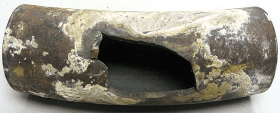
Numerous reactions are possible if the impurities reach the boiler, as previous equations have shown. However, the most problematic issue in many cases is represented by the following equation.
MgCl2 + 2H2O → Mg(OH)2↓ + 2HCl | Eq. 4-14
A product of this reaction is hydrochloric acid (HCl). While HCl can cause general corrosion in and of itself, the compound will concentrate under deposits where the reaction of the acid with iron generates hydrogen, which, in turn, can lead to hydrogen damage of the tubes. In this mechanism, atomic hydrogen penetrates into the metal wall and then reacts with carbon atoms in the steel to generate methane (CH4):
4H + Fe3C → 3Fe + CH4↑ | Eq. 4-15
The formation of the gaseous methane and hydrogen molecules induces cracking in the steel, greatly weakening its strength. Hydrogen damage is very troublesome because it cannot be easily detected. After hydrogen damage has occurred, the plant staff may replace tubes only to find that other tubes continue to rupture.
The potential for impurity ingress and acid formation as illustrated in Equation 4-14 requires neutralizing alkalinity in drum boilers to mitigate acid attack and hydrogen damage. As is outlined next, phosphate programs evolved to serve this purpose but also to protect against caustic damage. The chemistry has evolved over many decades.
Surprisingly, given the discussion about caustic attack above, one alternate program that has been adopted at some facilities is replacement of phosphate with caustic. Such chemistry requires careful planning.
THE CHALLENGES OF INDUSTRIAL BOILER WATER TREATMENT
Evolution of Phosphate Treatment
As has been noted, early phosphate programs with high phosphate concentrations induced caustic gouging in boiler tubes. Accordingly, chemists began to refine phosphate treatment to prevent caustic attack. One of the principal programs that came out of this effort was coordinated phosphate treatment. As evident from its chemical formula, the molar ratio of sodium to phosphate in tri-sodium phosphate is 3 to 1. In a coordinated phosphate program, enough di-sodium phosphate is added to maintain a Na/PO4 ratio between 2.8 and 2.2 to 1. The supplemental Na2HPO4 shifts the equilibrium of Equation 4-9, shown again below, to the left, which reduces the concentration of free caustic.
Na3PO4 + H2O ⇌ Na2HPO4 + NaOH | Repeat of Eq. 4-9
Although coordinated treatment was a significant refinement to phosphate programs, the evolution did not stop there. Researchers discovered a very important aspect of the sodium phosphates; they are reversely soluble at temperatures above about 250°F, and beyond this temperature will begin to precipitate (hide out) on boiler tube walls.
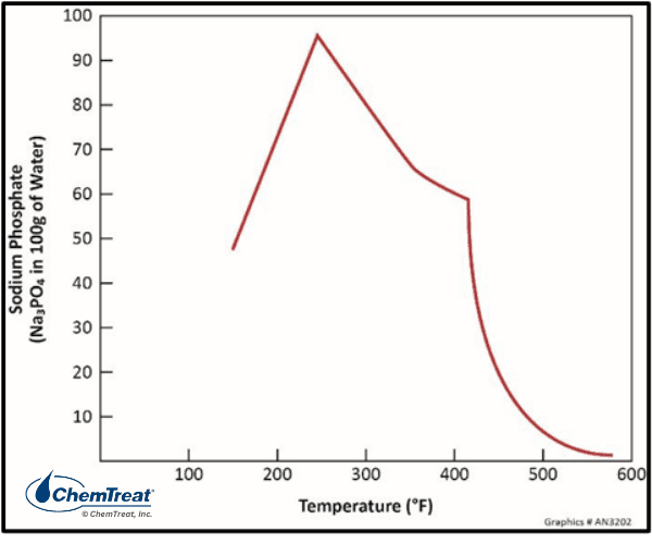
Figure 4.47. Solubility of tri-sodium phosphate as a function of temperature.
At the typical temperatures (600°F or greater) of modern high-pressure steam generators, sodium phosphates are only slightly soluble, and most of the chemical precipitates on boiler internals. Further research indicated that the precipitates in coordinated programs typically contained a lower sodium-to-phosphate ratio than that in the bulk boiler water, which influenced chemistry, as we shall see. These discoveries triggered a modification from coordinated to congruent treatment based on evidence that suggested the Na:PO4 ratio of phosphate deposits was between 2.3 and 2.6 to 1. This ratio was selected for the new treatment guidelines so any phosphate that did come out of solution would precipitate “congruently” and not affect chemistry.
As analytical chemistry capabilities improved and utility chemists began tracking chemistry more closely, data clearly showed that full load bulk water phosphate concentrations would often drop well below 1 ppm, especially in boilers operating at 2,000 psi and above. Hideout depletes the boiler water of the chemical designed to control scaling and corrosion.
Researchers also discovered that the phosphate compounds often precipitated incongruently, with deposit sodium-to-phosphate molar ratios of 2 to 1 or even lower. Hideout can be at its worst in a cycling unit. Consider a boiler at low load with phosphate treatment. As load is raised and heat fluxes increase, sodium phosphate deposition increases. Due to incongruent precipitation, the Na:PO4 ratio of the phosphate remaining in the solution rises, increasing the bulk water pH. The chemist may then add a di-/tri-sodium blend to raise the phosphate concentration and lower the pH, but this phosphate also hides out. When boiler load is reduced, the situation reverses and the precipitated phosphate re-dissolves. In this case, however, the sodium phosphate deposits, which have a low Na:PO4 ratio, drive the pH downward as they go back into solution. Coordinated or congruent phosphate treatment may be impossible to control in boilers that exhibit hideout.
Research has also shown that the low sodium-to-phosphate ratio deposits induce a phenomenon known as acid phosphate corrosion, which directly attacks boiler metal. This mechanism is now suspected as being responsible for much boiler tube damage previously thought to have been caused by caustic attack. Analyses indicate that sodium phosphates form a sodium-iron-phosphate complex with the magnetite layer, as a compound known as maracite.
Per these discoveries, the following list outlines important guidelines for phosphate treatment as compiled by a major international organization associated with the power industry. There is less consensus among other industries such as ammonia, refineries, ethylene, and other petrochemical plants. Some of these other industries continue to run congruent programs.
- Tri-sodium phosphate is the only recommended phosphate species. This reduces the potential for acid phosphate deposition. However, the free caustic concentration should not exceed 1 ppm to minimize the potential for underdeposit caustic corrosion. Computer programs are available, including in spreadsheet format, to optimize boiler water phosphate chemistry and reduce the chances for either acid phosphate or caustic corrosion.
- Recommended TSP concentration range of 0.3–2.4 ppm. The range is low to minimize hideout, but some residual is required in the event of a condenser tube leak or other contaminant ingress. Because makeup water treatment systems produce high-purity water, TSP’s primary function in the boiler is pH control, and even a slight concentration will do so. Recommended pH ranges vary modestly depending on boiler design but are typically within a 9.2–9.8 range.
- Because the low phosphate concentration provides limited protection against a condenser tube leak, the unit should be taken off-line when an upset is detected, and the upset condition corrected.
The issue of phosphate hideout led to the development of straight caustic feed as an alternative treatment for high-pressure drum units. However, very careful monitoring and control of this chemistry is needed to prevent underdeposit caustic attack. Similar to the conditions outlined in bullet #1 above, the free sodium hydroxide concentration in straight caustic programs should be limited to 1 ppm to protect the boiler internals.
Internal Treatment Methods for Industrial Steam Generators
Although industrial steam generators typically operate at lower pressures and temperatures than utility boilers, the choice of internal treatment can often be more complex. One influencing factor regards makeup water purity, and a common example comes from those units in which sodium softening is the primary makeup treatment method with no additional equipment for alkalinity removal. Low- and medium-pressure boilers often need only the alkalinity present in the feedwater to provide the necessary basicity for internal chemistry. Sometimes, however, additional alkalinity may be required. Two common alkalinity builders are sodium hydroxide and potassium hydroxide (KOH) for boilers <600 psi. These alkalis are often blended into boiler water chemical formulations at concentrations appropriate for the targeted boiler pressures. Potassium hydroxide is sometimes selected because of favorable blending properties. Potassium hydroxide also has a lower freezing point than sodium hydroxide at commercial concentrations. Safety is an important concern when handling these chemicals, especially if they are fed separately and not blended with other treatment chemicals.
Additional treatments are often required to prevent scale formation or fouling by impurities. A summary of treatment evolution and influencing factors is outlined below.
- Boiler pressures increased from 10–20 psi in the mid-1800s to 200 psi and greater by the 1920s.
- Patents were issued in 1857 for lignins and tannins as boiler treatments, in 1863 for di-sodium phosphate, and in 1887 for tri-sodium phosphate.
- Phosphates became widely accepted in the 1930s as a replacement for earlier, less science-based programs.
- Phosphate/polymer combinations emerged in the 1950s, with a key component being acrylate dispersants that reduced sludge production.
- Chelants came into use in the 1960s and were often combined with acrylate dispersants such as PAA (polyacrylic acid) or AMPS (2-acrylamido-2-methylpropane sulfonic acid). These were solubilizing programs and could provide very clean boilers, but chelants can induce significant corrosion if not properly applied.
- All-polymer programs have become popular for many applications. They can also cause corrosion without careful control but are less likely to induce corrosion than chelants.
The following discussion outlines in greater detail the progression of treatment programs and hints at the careful planning needed when selecting a program.
Carbonate Treatment Programs
An early treatment method for steam generators, especially for units with high feedwater hardness concentrations (>60 ppm calcium), carbonate programs actually induced precipitation. These programs have been almost entirely replaced with more advanced chemistry but may still occasionally be found. Remote (often temporary) mineral or petroleum extraction sites sometimes have boilers without any makeup water treatment, so deposition will by force occur.
Deposit-inducing programs preferentially precipitate calcium as calcium carbonate and magnesium as magnesium hydroxide or magnesium silicate. Calcium sulfate scale can be minimized by providing sufficient soda ash (Na2CO3) to react with any calcium sulfate entering the boiler through the makeup.
CaSO4 + Na2CO3 → CaCO3↓ + Na2SO4 | Eq. 4-16
Later it was learned that phosphate aids the preferential precipitation reactions.
Advantages and Disadvantages of Precipitation Programs
| Advantages | Disadvantages |
|---|---|
| 1. Suitable for boilers with extremely high feedwater hardness (>60 ppm). | 1. High TDS and TSS limit cycles of concentration in the boiler. |
| 2. Pressure limited to 450 psi. | 2. Cleanings (descaling) likely will be needed. |
Phosphate and Phosphate-Polymer Programs
The applications of phosphates for high-pressure boiler water treatment were outlined earlier, but they can be even more important for low-pressure boilers, particularly if hardness is present. As noted, phosphate and the alkalinity produced by its reaction with water will, with correct chemistry, react with hardness to generate relatively non-adherent calcium and magnesium precipitates that depart in the boiler blowdown.
The phosphate donors for such programs are typically either compounds of the orthophosphate ion PO4-3, generated from tri- and di-sodium phosphate, or perhaps a polyphosphate such as sodium hexametaphosphate or crystalline sodium tripolyphosphate/tetrasodium pyrophosphate. These latter compounds break down to orthophosphate in the boiler.
Modern phosphate programs for industrial boilers often include polymer conditioning agents, first developed in the 1950s and 1960s, to enhance deposit removal via boiler blowdown. The polymers function by altering the crystalline structure and increasing the solubility of compounds that precipitate from phosphate treatment. Additional details on these polymers are provided in the next section. A very important aspect of some polymers is their ability to keep iron oxide corrosion products in suspension, which can then be removed by blowdown. As previously mentioned, a problem that often plagues industrial boilers, and sometimes utility boilers, is transport of condensate return and feedwater corrosion products, usually iron oxides, to the boiler, with subsequent deposition on boiler internals.
Monitoring and control of phosphate feed and boiler water residual concentrations is straightforward with the aid of both continuous on-line and grab sample instrumentation. Grab sample analyses for filtered and unfiltered phosphate concentrations can assist in troubleshooting chemistry during upset conditions. Analytical methods are also available to monitor the concentrations of polymeric additives.
Feed of a phosphate/polymer formulation upstream of the boiler, perhaps even as far back as the deaerator storage tank, will maximize reaction time. However, this arrangement is not acceptable if a feedwater slipstream is utilized for steam attemperation. The injection of non-volatile compounds directly into steam can damage superheaters and turbines.
Advantages and Disadvantages of Phosphate/Polymer Programs
| Advantages | Disadvantages |
|---|---|
| 1. Good performance in a wide range of feedwater conditions, although all programs will perform more efficiently if hardness can be kept to low levels. | 1. Heavy deposition on boiler tubes can allow concentration of acid or alkali species that cause corrosion. |
| 2. Phosphate can serve over a wide pressure range from very low- to high-pressure utility units. | 2. At the temperatures in utility boilers, phosphate hideout becomes a distinct problem. |
| 3. Straightforward monitoring and control. | 3. Generation of precipitates requires good management of blowdown. |
| 4. Can handle hardness fluctuations better than all-polymer chemistry or chelants. | 4. In high-pressure units where steam-moisture separation becomes less efficient, some phosphate can carry over with steam and form loose deposits in superheater and reheater U-bends. These deposits can cause tube overheating. |
| 5. FDA/USDA approved. |
All-Polymer Programs
All-polymer programs were developed several decades ago with the goal of maintaining boiler tube cleanliness similarly to chelant programs, but without the potential of chelant corrosion. They are typically designed for systems with low hardness feedwater (<1.0 ppm calcium) and a pressure range of <900. As the name all-polymer indicates, the chemistry contains no inorganic phosphates or other alkalis. Well-designed programs have delivered outstanding performance with reduced corrosion risk. Successful deposit control involves several interrelated mechanisms, including sequestration; dispersion to keep precipitates very small in size and suspended in the boiler water; and crystal modification that alters the normal crystalline structure and inhibits formation of strong crystal bonds to metal surfaces.
These polymers typically have one or more of three active groups attached to the polymer backbone: carboxylates (R-COO–), sulfonates (R-SO3–), or a non-ionic species such as amide, which contains an oxygen and amine molecule. Specific compounds include polyacrylate (PA), polyacrylic acid (PAA), acrylic acid/acrylamido methyl propane sulfonic acid, (AA/AMPS), polymethacrylate (PMA), and polyacrylamide (PAM). Some common additives to these formulations include organic phosphates like hydroxyethylidene diphosphonic acid (HEDP) and a newer compound, polyisopropenyl phosphonic acid (PIPPA). PIPPA serves as an iron dispersant at pressures up to 1,800 psi.
The correct formulation will vary depending on makeup water purity, boiler pressure and operating characteristics, condensate return chemistry, and other variables. Polymers that work well for systems with sodium softened makeup need to be carefully controlled for boilers with high-purity makeup and condensate return. Though the corrosion risk of these compounds as compared to chelants is greatly minimized, some corrosion may still be possible, especially in higher purity waters where overfeed could attack the base metal.
Breakdown products from the polymeric dispersants range from CO2 to ammonia to short-chain organic acids.
Advantages and Disadvantages of All Polymer Programs
| Advantages | Disadvantages |
|---|---|
| 1. Good performance over a wide range of feedwater conditions and boiler pressures. | 1. Alkalinity requirements increase potential of caustic attack in high-pressure systems. |
| 2. Straightforward monitoring and control. | 2. Generation of precipitates requires careful blowdown management |
| 3. FDA/USDA approved. | |
| 4. Carrying higher residuals not corrosive in non-upset feedwater conditions |
Chelant Programs
Chelant chemistry for steam generator treatment became somewhat popular in the 1960s, but these programs are rare today, with phosphate and polymer treatment methods being more common.
The study of chelants can involve a deep dive into inorganic chemistry, but from a practical standpoint, each chelant molecule typically bonds with a metal ion through four or six reactive sites on the chelant. These bonds can be very strong, preventing metal ions from undergoing other reactions such as scale formation in the fluid.
Ethylene-diamine-tetraacetic acid (EDTA) is by far the most well-known chelant and has found use in a variety of applications, including in the health industry for treating people suffering from lead poisoning.
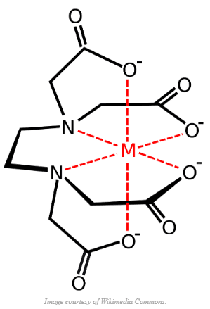
An alternative is nitrilotriacetic acid (NTA), but it is rarely utilized. EDTA stoichiometrically requires 3.8 ppm per 1 ppm of hardness, is stable to 400 psi, and has full FDA approval for these types of applications.
The order of EDTA affinity for cations is: Fe+3 → Cu+1/Cu+2 → Fe+2 → Ca+2 → Mg+2. Thus, the compound can effectively sequester iron that enters the boiler.
Chelants should be injected continuously to the feedwater through a stainless-steel quill, typically downstream of the feedwater pumps to protect pump impellors. Rigorous deaeration of the feedwater is required, as the combination of oxygen and the chelant could cause severe corrosion of feedwater piping, heat exchangers, and other equipment.
Controlling chelant chemistry is more challenging than phosphate or phosphate/polymer chemistry. Concentrations of either EDTA or NTA typically are maintained well below 20 ppm in the boiler water and usually in the 3–6 ppm range, as otherwise corrosion could be problematic, particularly at the rolled tube ends in boiler drums.
Testing procedures for chelant concentration are available but have poor reproducibility and are difficult to perform. Mass balance calculations may be needed to accurately determine feed rates. It is also important to maintain proper alkalinity concentrations in the boiler water. ChemTreat personnel can provide guidelines for individual applications.
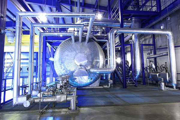
REFINERY SAVES $238,000 ANNUALLY WITH TITAN360®
Boiler Layup
Whenever a unit comes off-line, air ingress may occur at even the smallest openings within the water/steam network, particularly as the unit cools and the water volume shrinks. Oxygen can then attack at localized areas and cause serious damage to tubing, piping, and other components. The most problematic issues include:
- Pitting of carbon steel (and copper alloys in those units where they still exist) in the feedwater system, boiler, and superheater/reheater circuits.
- Enhanced corrosion fatigue (CF) and stress corrosion cracking (SCC) in boiler circuits, which are often initiated by pitting.
- Carryover of corrosion products to the boiler, where deposition, particularly of porous iron oxides, can lead to underdeposit corrosion (UDC) during unit operation.
- Pitting of turbine blades in the last low-pressure stages where salt deposition occurs. Pitting here also leads to CF and SCC.
As this list indicates, proper corrosion protection covers the entire steam generating system, not just the boiler. Reference 16 provides a succinct summary of layup needs:
Protection strategies should take into account site-specific factors, operational requirements, and unit design. A seamless transition from service through shutdown, into the out-of-service or layup period, and through the subsequent unit startup must be factored into the strategy. Proper storage of all major components or systems should be incorporated into a comprehensive layup procedure for the unit. The shutdown and layup periods should be viewed as a continuation of the good water chemistry practices used during operation. The primary purpose of the cycle chemistry is to provide protective oxide surfaces on all components throughout the steam and water circuits in order to minimize corrosion and reduce concentrating and performance-robbing deposits on heat transfer and aerodynamic surfaces.
A key extract from the quote above is “operational requirements.” During much of the last century, base-load operation of large, coal-fired power plants was the norm. Now, well into the 21st century, with the significant expansion of renewable energy, most fossil-fired plants, whether they are remaining coal units or combined-cycle power generators, operate on a cycling mode, with frequent startups and shutdowns. This aspect plays an important role in selecting layup techniques.
Significant layup factors include:
- Type and duration of outage
- Short to intermediate outage per load fluctuations
- Forced outage due to an equipment issue such as a boiler tube failure
- Scheduled maintenance outage
- Long-term storage
- Anticipated lead time before startup
- Metallurgy and equipment present in the boiler and condensate/feedwater circuits
- Potential for freezing
- Local atmospheric conditions (i.e., relative humidity) and risk of acid formation on the boiler fireside.
- The ability (and desire) of plant personnel to install a nitrogen blanketing system or utilize dehumidified air for dry layup.
Choosing the Correct Layup Method
A common set of criteria for outage duration is as follows:
- Short-term: Overnight or perhaps over a weekend
- Intermediate-term: Longer than a weekend to a week or so
- Long-term: A few weeks to months
Wet methods are often selected for short and intermediate layups, as the steam generator must be available for a quick return to service. When possible, and this especially applies to short, overnight outages, maintaining heat in the unit by keeping circuits sealed will minimize air ingress. A common term is “bottling up” the unit. If possible, a vacuum should be maintained on the steam-side of the condenser to prevent ambient air in-leakage to the condenser and especially the LP turbine. For outages that last several days, additional methods are necessary to protect the unit but have it available for quick startup. In some plants with multiple steam generators, it may be possible to import steam from an operating unit to keep the steam generator warm. Or the plant may have an auxiliary boiler to provide heating steam. Common steam tie-in locations include the boiler drum and deaerator vents. For conventional units, feedwater heater vents are another option.
Regarding utility unit wet layups, recall the previous discussion of AVT(R) and AVT(O) operational chemistry earlier in this chapter. AVT(R), which is necessary for feedwater systems of mixed metallurgy, utilizes a combination of ammonia and a reducing agent/oxygen scavenger. For systems of all ferrous metallurgy, AVT(O), which excludes the reducing agent, is the recommended choice. A general recommendation for units on either of these operational chemistries is as follows:
Keep the chemical oxidation-reduction potential of water in the cycle the same during all operating conditions. This principle refers not only to excluding air but also to maintaining chemical residuals that exist during operation. If reducing agents (such as hydrazine) are used during normal operation, they should be used during layup. If they are not, they should not be introduced just for layup (unless extenuating circumstances exist that should be reviewed.)
What are those extenuating circumstances? They involve acceptance or rejection of a protective method that is strongly recommended but often not adapted by plant management: nitrogen capping, otherwise known as blanketing.
Nitrogen Blanketing
As has been noted, if the steam system is allowed to cool with water remaining, air can be drawn in that then generates localized and potentially very damaging corrosion. The application of nitrogen at various strategic points in the steam-generating system when the boiler cools to 5 psig pressure will inhibit the in-leakage of air and establish an inert atmosphere. The following table, extracted and edited from Reference 16, provides a general overview of the shutdown and wet layup process as developed for conventional steam-generating power plants.
Table 4-4 – Wet Layup Procedures for Conventional Units with Nitrogen Blanketing
| Initial Step | Allow boiler to cool to 5 psig |
| As Boiler is Cooling from 5 psig, Perform the Following Steps | Just prior to or during shutdown, ensure the boiler pH is >9.5. If the unit is on AVT(R) feedwater treatment, the reducing agent residual can be increased. |
| Establish a nitrogen blanket on the deaerator as steam to the deaerator is isolated. | |
| Establish a nitrogen blanket on the shell side of the feedwater heaters as pressure to the heaters is isolated. | |
| Put the reheater under vacuum by opening the reheater drain lines while maintaining condenser vacuum. | |
| Add nitrogen to the reheater to break vacuum on the condenser. (It is important not to let air enter the LP turbine if vacuum must be broken.) | |
| Open the nitrogen supply to the superheater to fill the boiler and superheater as steam collapses. | |
| Establish a nitrogen blanket on (or drain and dry) any drip tanks, auxiliary condensers, or other wet equipment. | |
| Place warning signs on all nitrogen-containing equipment and ensure lockout-tagout procedures are strictly enforced. |
Adherence to these guidelines will provide protection to the entire steam-generating unit. Safety is critical, as although nitrogen is not poisonous (our atmosphere contains 78% nitrogen), the potential for rapid asphyxiation is possible if entering an enclosed area with limited oxygen content.
The procedures for nitrogen capping HRSGs would typically be similar. One notable difference is that most HRSGs have no feedwater heaters apart from a deaerator, so that step can be eliminated. Given the frequent shutdowns and startups of many combined-cycle units, nitrogen capping can provide excellent protection of the HRSGs during the short turnaround times. Reference 17 provides details on the nitrogen capping system of a combined-cycle plant in the Midwest. This facility has a nitrogen generator for the production and storage of the gas, which protects the plant’s two HRSGs during wet layups. Also employed at this facility for wet layup protection is a circulating system that can move the treated condensate and boiler water throughout the water-side circuits of the HRSGs. The circulating system of any unit should be equipped with at least one sample tap and valve so samples can be collected on a regular basis, such as once per week or month to evaluate conditions. If the treatment chemical concentration has dropped below a pre-selected limit, fresh chemicals should be added.
At many plants, management may balk at the expense of installing nitrogen blanketing systems without realizing the technology could easily pay for itself if in place. Concerns about confined-space safety also sometimes factor into these decisions. For units on AVT(R) feedwater chemistry, some protection remains possible by installing the aforementioned circulating system to move treated water through the boilers and condensate/feedwater systems. This helps minimize stagnant sites that induce localized corrosion. The pH is adjusted above 9.5 with ammonia or alkalizing amine, with supplemental non-volatile reducing agent feed. The situation becomes more complicated for AVT(O) systems without nitrogen blanketing, as the use of a reducing agent during shutdown violates the principle of maintaining the same oxidation state with the unit on or off.
Dry Layup
When a unit comes off-line for an extended period, and without the need for a quick startup, dry layups are usually recommended. If conducted properly, one of the three conditions for corrosion is eliminated by removing free moisture. Two methods to keep moist air from causing corrosion during a dry layup are the feed of warm, dehumidified air (DHA) to the unit or nitrogen blanketing where a much larger volume of nitrogen is needed as compared to a wet layup. This section focuses primarily on DHA dry layups. General recommendations are outlined in Table 4-5 below, again extracted and edited from Reference 16.
Table 4-5 – Dry Layup Procedures for Conventional Units with DHA
| Initial Step | Allow boiler to cool to 25 psig. |
| As Boiler is Cooling from 25 psig,Perform the Following Steps | Drain the deaerator storage tank as soon as steam to the deaerator is isolated. |
| Open the feedwater shell-side drains while the heaters are hot. | |
| Put the reheater under vacuum by opening the reheater drain lines while maintaining condenser vacuum. | |
| Drain the condenser hotwell completely while it is still hot. | |
| Circulate dehumidified air through the LP turbine and out of the hotwell. | |
| Drain all feedwater piping, drip tanks and other related equipment. | |
| Drain the boiler when the pressure reaches 25 psig. Dry compressed air can be utilized to assist with draining. | |
| Introduce DHA to the boiler, superheater, deaerator, and related equipment to establish a relative humidity of <35%. |
A critical aspect of this process is draining equipment while it is still hot. This allows for flash drying of most moisture that would otherwise remain in the unit and potentially become saturated with oxygen. Flash drying can be particularly important for removing moisture from non-drainable superheaters.
Another critical step is the circulation of warm DHA through as many circuits as possible. First and foremost is draining the condenser hotwell completely and feeding warm air through the condenser and into the LP turbine. Even at plants with excellent water/steam chemistry programs, minor carryover of impurities to the turbine still occurs. These compounds precipitate on the last rows of the LP turbine where the first moisture (commonly termed “early condensate”) begins to form before steam discharge to the condenser. These deposits, primarily sodium chloride and sulfate, are not problematic during normal operation. However, if the condenser is opened and the turbine becomes exposed to a humid atmosphere, the deposits will absorb moisture that, in turn, may cause pitting of the turbine blades and rotor. Subsequent unit operation can advance the pitting into corrosion fatigue and stress corrosion cracking. These issues are outlined in a later section.
Carrying the idea of warm air circulation a step further, EPRI previously published guidelines on methods to circulate warm air throughout the entire steam generating system. A key aspect of this method is the ability to prop open main and reheat steam stop valves. Ideally, DHA is introduced at the condenser or LP turbine and flows counter-currently through the steam system to the boiler and then to the condensate/feedwater system. DHA circulation can also be arranged on multi-pressure HRSGs.
A somewhat similar set of procedures as outlined in Table 4-5 above can be developed for dry layup with nitrogen blanketing, with the first steps still flash drying. However, several factors require extra consideration. One, of course, is the much greater amount of nitrogen needed to fill an empty steam generator rather than capping a unit with water at normal levels. The second is safety. It is obviously much easier for plant personnel to enter a vessel that has previously been drained of water. Clear warnings and lockout/tagout procedures must be in place. However, for many long-term outages such as those for annual maintenance, nitrogen blanketing is impossible due to work required on boiler or superheater tubes, or other equipment. DHA circulation is still a viable option in those situations.
Vapor phase corrosion inhibitors (VPCI) offer another potential layup option. These volatile compounds first vaporize and then condense on ferrous and non-ferrous components to form a strong surface bond. The monomolecular layer inhibits electrochemical corrosion reactions. The ability to seal equipment in which VPCIs have been placed is important to maximize vapor concentration and establish a complete protective layer. Depending on the purity requirements of the steam cycle, steam blows and/or increased blowdown at startup may be necessary to remove the compounds from the cycle. VPCI is a very valid consideration for dry layup of steam generator waterside and fireside equipment if the components can be properly sealed from the atmosphere.
Chemical Treatment for Industrial Steam Generator Layup
As noted above, volatile chemicals such as ammonia or neutralizing amines, and, in certain cases, reducing agents/oxygen scavengers, are required for high-pressure utility and industrial boiler layups, with high pressure in this instance defined as >900 psi. The primary reason for volatile chemical treatment, and this applies both to layup and normal operation, is that most of these high-pressure steam generators employ direct spray attemperation of main and reheat steam temperature control. This is a direct path from the feedwater to steam, and the use of non-volatile compounds could cause severe problems in superheater/reheater circuits and especially turbines.
While nitrogen blanketing is a possibility for wet layup of industrial units, this method is often considered too expensive or laborious. For extended wet layups of low- to intermediate-pressure boilers with no direct steam attemperation, it is common to dose with sodium sulfite (Na2SO3) at up to 100 ppm concentration to react with dissolved oxygen. Several possibilities are possible to control pH. The alkalizing amines described earlier in this chapter are one option, but for units without superheaters, another possibility is hydroxide alkalinity to maintain a pH of 11.0. Corrosion data suggests that this is a good pH to minimize carbon steel corrosion at ambient conditions. Because chemical mixing can be challenging once the unit has shut down, chemical injection is typically recommended up to 30 minutes before shutdown. This allows thorough mixing of layup chemicals. Sulfite levels should be initially maintained at 200 ppm due to the demand created by air ingress. Once dissolved oxygen is consumed, maintain 100 ppm of sulfite.
Fireside Protection
The boiler fireside also requires attention during layup. Many fuels contain sulfur, which can combine with ambient moisture and form strong acids at metal surfaces. The primary goal of gas side layup is to maintain warm, dry conditions above the ambient dew point. This can be accomplished with portable heaters to keep the unit warm, and by sealing the exhaust stack to prevent rainwater and outside air from entering. In cold weather, closing the stack damper helps maintain heat within the unit. Some plant procedures call for deposit washing during outages of certain units such as auxiliary boilers, but the waste streams can be quite acidic and must be disposed of properly.
Returning the Boiler to Service
Space limitations prevent a detailed discussion of boiler startup procedures, which can be quite variable depending on whether the unit is being returned from wet or dry layup, but several general guidelines are helpful.
- If returning from a wet layup where chemical dosages were increased to protect the unit, some draining combined with purified makeup replacement may be required to reach operational chemistry limits.
- When a boiler is returned to service from a dry layup, care is needed to minimize potential corrosion from the fill water. Several methods to accomplish this are outlined below.
- When filling a boiler for startup, it is important that the procedures include the addition of the steam generator chemicals so the proper chemistry is in place as the boiler is heated and eventually placed on-line. A key aspect in this regard is establishing a boiler water pH >8.0 before firing. For the many drum boilers using phosphate treatment, this means establishing the proper phosphate concentration in the boiler water.
The first item can be particularly important in units with copper alloys in the condensate/feedwater system. Mostly, these situations are limited to older, conventional units with multiple feedwater heaters. The combination of oxygen and ammonia can be quite corrosive to copper and its alloys.
With regard to filling a boiler from dry layup, some of the efforts in protecting the unit from corrosion can be negated by filling from an ambient-temperature, atmospherically-vented condensate storage tank. Steam sparging, if the equipment is in place, of such tanks before boiler filling will greatly reduce the D.O. concentration. At the combined-cycle plant outlined in Reference 17, a gas-transfer membrane treatment system is in place to reduce the dissolved oxygen concentration of makeup water to 10 ppb. Even with deoxygenated makeup, as the boiler is being filled, oxygen can enter the condensate from air in the boiler. Filling the boiler from the bottom of the unit reduces air exposure.
At startup, it is important to follow the manufacturer’s guidelines regarding heating rates, alternatively known as ramp rates. Excessive firing can damage equipment, including superheaters and reheaters (if present), and turbines. Given the high cycling duty of many boilers now, these issues are accentuated. The result may be shortened asset life and increased forced outages from stress-induced failures.
Chemical Cleaning of Steam Generators
During unit operation, boiler tubes and internals accumulate deposits. With consistent high-purity makeup and clean condensate, the materials primarily consist of iron oxide corrosion products from elsewhere in the system. Copper may also be present if the condensate/feedwater system has heat exchangers with copper alloy tubes. If the unit is plagued with makeup water upsets or heat exchanger leakage to the condensate return, deposits can range widely from hardness compounds to organics.
As has been noted, deposits reduce heat transfer and can induce underdeposit corrosion. Sources of contamination and other problems should be quickly identified and corrected to minimize deposition. But even then, periodic boiler chemical cleanings may be necessary to maintain tube integrity and life expectancy. Some of the important steps in determining the need for chemical cleaning include:
- Maintain records of condensate/feedwater upsets with data on the nature and concentration of impurities and duration of the upset.
- Conduct visual inspections of boiler internals and other system components during scheduled maintenance outages.
- Also during outages, collect tube samples and have deposits analyzed for the amount (deposit density, typically measured as grams per square foot) and constituency.
Other steps are also necessary, but this data provides critical information on the need for chemical cleaning and the deposits to be removed. The latter is extremely important in the selection of the proper cleaning solvents and process. For example, if the deposits are mostly iron oxide, a relatively benign chelant cleaning (some form of EDTA is a common choice) is possible with some heating of the cleaning solution. On the other hand, if impurity ingress has caused silica deposition, an inhibited hydrochloric acid cleaning with supplemental addition of ammonium bi-fluoride may be necessary. Extra care is required in handling these solutions, which are not only aggressive to mineral deposits but human flesh as well.
Cleanings are complex processes that require preparation of detailed procedures with the input of plant operators, technical personnel, and management. The procedures should be developed with the assistance of the cleaning contractor selected for the project.
Also of note is that cleanings on multi-pressure HRSGs can be significantly more complicated than conventional steam generators because of the complex geometry of the HRSGs. All the more reason to establish a comprehensive water/steam chemistry program from the outset to minimize deposit formation.
Steam Systems and Chemistry
While condensate/feedwater and boiler water chemistry control are quite important, perhaps even more critical is the protection of the steam system, particularly if the steam powers turbines. Steam turbines are highly tuned mechanical devices that, if a failure occurs from a mechanical or chemistry-related issue, are extremely expensive to repair or replace, and may hobble a plant for months or longer. Additionally, and this includes industrial steam generators without turbines, carryover of solids into steam can induce deposition and corrosion in superheaters, which may cause failures in these heat exchangers. Steam chemistry control is, therefore, an integral part of any steam generator chemistry program. The next section outlines fundamentals regarding steam turbines followed by a discussion of methods to protect steam systems and turbines from impurity deposition and corrosion.
Steam Turbines
As has been discussed, steam that exits the boiler drum is “saturated steam” (or wet steam) and cannot be directly injected into a turbine because the immediate formation of water droplets would cause excessive erosion of turbine components. Steam superheating is thus required. The thermal energy in superheated steam is converted into rotational mechanical energy as the steam passes through the turbine stages. The number of stages differs depending on the type and design of the turbine, but most industrial turbines have several stages, and some have as many as 20. A stage consists of stationary blades (nozzles) and rotating blades, aka buckets. The nozzles direct the steam to the rotating blades and convert pressure (potential energy) to velocity (kinetic energy).
The turbine rotor is connected to a generator set to produce electricity in a power plant. In the petrochemical industry, many steam turbines drive compressors.
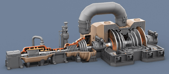
While separate turbine and generator rotor assemblies are possible, the most common is for the turbine and generator set to be combined on a single shaft. At the generator end, magnets attached to the rotor spin through a series of fixed “stator” coils to produce electricity. Steam turbine rotors come in three main types: “welded,” “shrunk-on-disc,” or “solid” (“monobloc”). A welded rotor has each individual disc welded to the rotor. As the name shrunk-on-disk implies, the discs are shrunk-fit onto the rotor. A monobloc rotor is a design where the entire shaft and blade assembly is manufactured from a single forging. The welded-rotor design is typically most reliable. Rotor failures usually occur at the low-pressure end, where stresses are the highest, as will be further examined in a later section of this chapter.
The entire assembly of rotor, blades, buckets, and shrouds and the steam flowing through the turbine is protected and contained with a cover plate, i.e., the turbine casing.
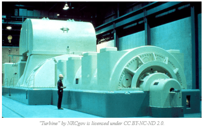
Many turbines have both impulse and reaction blade stages, whose basic designs are outlined below.
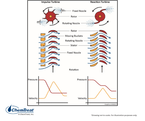
In an impulse stage, jets of steam passing through fixed nozzles directly impact the rotor blades and impel rotation. The velocity of the steam emerging from the nozzles is approximately twice the blade velocity. In a reaction turbine stage, the nozzles are not fixed but mounted on the turbine shaft. The steam flows through reaction blades with lower pressure drop and lower velocity increase than in impulse stages. Thus, more rows of moving blades are needed than in an impulse turbine. The most efficient turbines, especially for large applications, employ both impulse and reaction stages.
Two measurements are common for tracking pressure drop across a turbine stage: pressure ratio and the percent reaction. Pressure ratio is the pressure at the stage exit divided by the pressure at the stage entrance. Reaction is the percent isentropic enthalpy drop across the rotating blade or bucket compared to the total stage enthalpy drop. Some manufacturers utilize percent pressure drop across the stage to define reaction.
A turbine may have several sections of different pressures. The final design configuration is determined by the actual use or purpose of the turbine. Examples include cogeneration, electricity production only, or a backpressure turbine to drive a turbo blower. As Figure 4.16 and Appendix 4-1 indicate, typical power plant steam turbines have three separate sections. Main steam produces a portion of the total power in the high-pressure turbine. After completing work in the HP stage, the steam is returned to the boiler to be reheated to its original temperature, although the pressure is much lower due to the work done in the HP stage. The reheated steam, which now has a higher enthalpy, then passes through the IP stage, where it generates more power before flowing through crossover piping to the LP turbine. The LP turbine may produce up to 50% of the power generated in a large unit. Exhaust steam from the LP turbine is converted to liquid in the condenser for return to the boiler.
A quick note about reheating: this process improves overall boiler efficiency slightly, but, more importantly, reduces the amount of water droplet formation in the last stages of the LP turbine. Excessive condensation in this section can cause erosion of the turbine blades.
Condensing and Backpressure Turbines
The figures above illustrate condensing turbines. Whether water-cooled or air-cooled, the condensers convert all the turbine exhaust steam to liquid. Most common are surface condensers in which the steam passes over thousands of relatively small-diameter tubes through which cooling water is circulated. The steam-to-condensate conversion reduces the volume by a factor of well over 10,000. The steam collapse produces a very strong vacuum inside the condenser shell, and this induced vacuum pulls steam through the turbine, maximizing power output. The condensate collects at the bottom of the condenser shell in a compartment known as the hotwell. From there the condensate returns to the boiler.
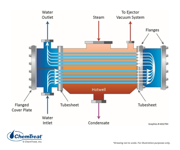
Automatic controls maintain water level within a pre-set range in the hotwell by moving condensate to and from a separate storage tank. Condensate additions or extractions are automatically adjusted based on changes in boiler load.
Although condensate is generally of high purity, it does contain non-condensable gases, most of which enter due to the strong vacuum in the condenser that pulls air in through even the smallest openings. These gases will, in time, grow in concentration and increase the turbine backpressure, thereby lowering efficiency. Accordingly, steam surface condensers are equipped with an air removal compartment to which an external vacuum is applied either by steam-jet ejectors or, more commonly, vacuum pumps. Steam is then exhausted to the atmosphere.
A point to be noted is that at an increasing number of plants, air-cooled condensers (ACCs) are being selected as a water conservation method. Because the density of air is so much lower than water, ACCs must be massive to achieve similar cooling.
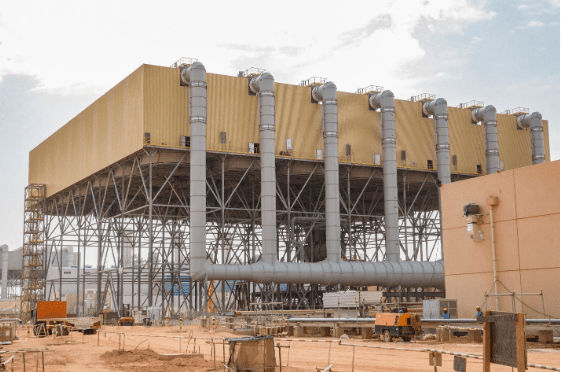
Furthermore, ACCs can only approach the dry-bulb temperature of the ambient air, whereas water-cooled condensers supplied by a cooling tower approach the wet-bulb temperature of the tower. In warm weather especially, efficiency losses are greater with ACC units.
Condensing turbines primarily serve power generation applications, including fossil and nuclear. A difficulty with condensing turbines from an energy efficiency standpoint is that well over half of the heat input to the boiler water is required to convert water to steam, i.e., the latent heat of vaporization. Most of this energy is lost in a standard condenser. However, in cogeneration and combined heat and power (CHP) applications, where the steam is extracted before reaching the saturation point and is utilized for direct heating, much of the latent heat is recovered rather than wasted. Such turbines are classed as “non-condensing” or “backpressure” turbines.
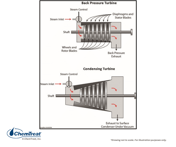
Non-condensing turbines operate at a design backpressure set by the process requirement. They are common in a vast array of heavy industries: petrochemicals, pulp and paper, primary metals, etc., and are often used to drive centrifugal equipment such as turbo blowers, turbo compressors, and so forth.
Cogeneration steam is often produced in specialized boilers, including HRSGs, and is first expanded through a turbine to produce electrical energy. Some ports for steam extraction to plant processes may exist within the turbine. The main turbine exhaust is not condensed but serves other heating applications. For example, consider a turbine with a 600-psi inlet steam supply and an exhaust pressure of 110 psi. The differential pressure (DP) is 490 psi, which produces electrical energy. However, the exhaust steam still contains superheat and may be used to drive other smaller turbines or for direct heating of equipment such as reboilers, process heat exchangers and reaction vessels, deaerators, etc. In this type of turbine, the exhaust must be maintained at a constant pressure to prevent fluctuations that would affect the turbine speed.
Other Types of Steam Turbines
Topping turbines are non-condensing machines that can be added to older, medium-pressure plants. Topping turbines receive high-pressure steam from new boilers, with the exhaust steam of the new turbine set at the same pressure as the old boilers. This steam supplies the existing turbines.
In a radial-flow turbine, steam flows outward from the shaft to the casing. These turbines are utilized for special applications and are common in Europe.
Additional Steam Turbine Details
Steam turbines are complex machines that must be designed, manufactured, and maintained to strict tolerances to meet and preserve the design power output and unit availability and reliability. This section briefly outlines additional turbine details for non-experts.
Bearings and Lubrication
Two types of bearings serve to support and stabilize turbine rotors: journal and thrust bearings. A journal bearing consists of two half-cylinders that enclose the shaft and are internally lined with Babbitt, a metal alloy usually consisting of tin, copper, and antimony. Turbine lubricating oil is applied to the journal bearings, and the rotor spins on the thin film of oil produced thereby. Thrust bearings are located axially on the turbine rotors. The decrease in steam pressure as it flows from high to low pressure induces a force on the turbine that must be counteracted, which is the function of these bearings. High-pressure oil is also applied to these bearings for lubrication. Turbine lube oil must be carefully filtered to remove solid particles. Lube oil systems normally include specially designed centrifuges or other coalescing devices to remove water from the oil. Even so, microbes will grow in turbine lube oil tanks that may, at times, necessitate off-line cleaning.
Seals
Within each turbine shell, the disks with the longest blades must have a very tight tolerance to the casing to prevent steam leakage. These shaft seals consist of a series of ridges and grooves around the rotor and the housing, which present a long, tortuous path for any steam leaking through the seal, hence the commonly known name of labyrinth seals. The small amount of steam that does escape is collected and returned to a low-pressure part of the steam circuit, typically the gland steam condenser, which drains to the main condenser.
Turning Gear
Operating on “turning gear” during unit shutdowns is standard for large steam turbines. The slow rotation maintains balance on the rotor and prevents bowing from the heavy weight if the rotation was completely halted. Rotation also allows the temperature to equilibrate throughout the rotor as it cools.
Turbine Vibration
Power turbines rotate at 3,000 or 3,600 rpm depending on whether the plant produces 50-Hz or 60-Hz frequency electricity. Minimizing shaft vibration, especially during startup, is critical to prevent turbine damage. Most medium and large turbines have sensors that measure vibration to ensure proper startups and subsequent operation at load. Prompt detection of any problems allows for shutdown prior to serious damage.
Steam Chemistry
Two important properties of steam are its quality and purity. Sometimes they are incorrectly interchanged in steam discussions. Steam quality refers to the amount of moisture in steam. For example, steam with a quality of 0.95 contains 5% moisture. In boilers with superheaters, the steam entering the turbine or other process equipment has a steam quality of 1.0 plus much superheat energy to keep it dry, although it drops slightly below that level in the last rows of the low-pressure turbine as early condensate forms.
As the name implies, steam purity refers to the level of impurities within the steam. Contaminants can enter steam through several possible pathways:
- Mechanical carryover in the drum
- Vaporous carryover
- Direct introduction from attemperator sprays for steam temperature control
- Decomposition of certain water treatment chemicals, most notably neutralizing amines
- Exfoliation of iron oxides from steam piping
Mechanical Carryover
Mechanical carryover is usually the issue of greatest concern. Steam that accumulates in the boiler drum will contain entrained moisture. To a lesser or greater extent depending on the boiler design, pressure, and other factors, the steam drum will have a combination of internal water-steam separators to remove entrained water droplets and return them to the drum liquid. The figure below shows some of the most common separating devices.
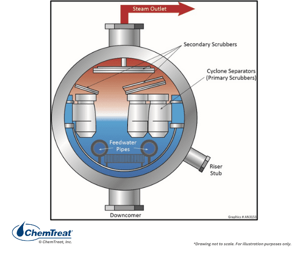
Even with well-designed separators, a small amount of mechanical carryover still occurs, with pressure being a significant influence.
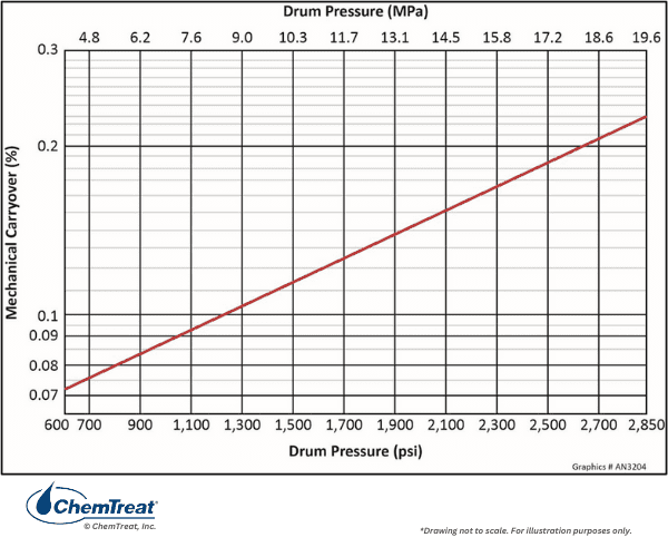
This effect, in turn, plays a part in boiler water chemistry guidelines, as boiler water in drum units may cycle up anywhere from 20 to 200 times. Even slight carryover can introduce unacceptable concentrations of contaminants to steam if not monitored and controlled. Some compounds, most notably sodium hydroxide and sodium chloride, can cause serious corrosion of turbine blades and rotors. Most boiler manufacturers design for 0.2% maximum mechanical carryover, a specification that can usually be met, although, as Figure 4.57 indicates, pressure has a direct influence.
System upsets and equipment wear can induce carryover excursions in drum boilers. The list below re-emphasizes the most prominent mechanisms that lead to excessive carryover.
- Damaged steam separation equipment
- High dissolved solids content in the boiler water
- Foaming compounds such as organics in the boiler water
- Poor drum design (e.g., small drum size, inadequate separator design)
- High drum water level/malfunctioning drum level instrumentation & control
- Excessive load ramp rates
Vaporous Carryover
A few compounds will carry over into steam as a vapor, most notably silica. Silica is not corrosive, but silica deposits can impact the aerodynamics of turbines and reduce output. The extent of silica carryover is a direct function of boiler pressure and becomes much more pronounced as pressure increases. For high-pressure utility units, the recommended silica limit from the makeup system is 10 ppb to keep the compound from accumulating in the drum to concentrations that would induce excessive carryover.
Copper compounds will also carry over vaporously to steam, especially at pressures above 2,000 psi. The copper then deposits on high-pressure turbine blades and reduces aerodynamic efficiency. Copper carryover was, at one time, a significant issue with coal-fired units, as many of these had copper-alloy feedwater heater tubes. The retirement of many coal-fired plants and their replacement with combined-cycle generation has, in large measure, reduced this problem.
Attemperator Impurity Introduction
Steam attemperation offers a direct pathway for impurities to enter superheaters and turbines and is yet another reason why units should not be operated with a condenser tube leak. Contaminant ingress can be detected by both steam and feedwater on-line instrumentation.
Decomposition of Some Treatment Chemicals
A previous section discussed the long-time use of ammonia as the primary chemical for feedwater pH control in power units, and the basic equation is shown again for reference.
NH3 + H2O ⇌ NH4+ + OH–
In many lower-pressure non-utility boilers and in the low-pressure evaporator of HRSGs, ammonia will flash off with steam and provide little protection against such phenomena as two-phase FAC. As noted, alkalizing amines are sometimes selected as a supplement or even a direct replacement for ammonia as the feedwater pH conditioning chemical. However, in superheaters, the amines will decompose to small-chain organic acids, most predominantly acetic and formic acids.
Iron Oxide Intrusion
Steam piping and superheater/reheater tubing also develop an iron oxide layer during operation. Excessive temperatures and frequent cycling can generate thick oxide layers that may spall in various locations. The particulates are then carried downstream to the turbine. Even though turbines have inlet screens for protection, fine particulates can still enter the turbine and cause abrasion, particularly in the high-pressure stages.
Steam Sampling
Accurate and reliable steam analyses are a critical aspect of protecting superheaters/reheaters and turbines. Representative steam sampling is integral to accurate data gathering. The first step in representative sampling is choosing the correct sample locations. The ideal spots will have the proper nozzle orientation and be situated in straight run piping free from the influence of upstream or downstream flow disturbances, as specified in ASME PTC 19.11.
A key aspect of steam extraction for analysis is isokinetic sampling, as illustrated below.
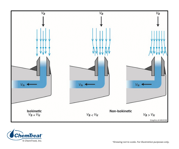
Isokinetic extraction collects the sample at the same velocity and directional vector of the bulk fluid.
Figure 4.58 below outlines the ideal steam sampling and conditioning arrangement.
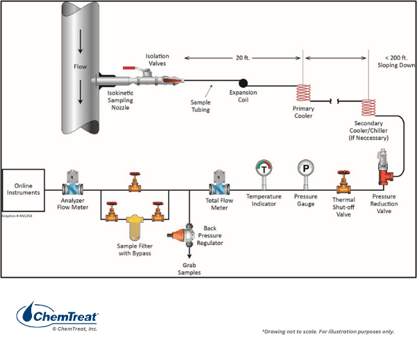
316 stainless steel or better is recommended for the construction of sample nozzles, tubing, and all other components. Lesser material grades, such as carbon steel, can accumulate or generate impurities that compromise sample integrity. The orientation of the sample line from the nozzle to the point of retrieval/analysis should have a continuous downward slope. The sample line should be sized so the sample flow linear velocity is 3–6 feet per second.
Samples should be cooled to 77°F (25°C) and, if possible, close to the extraction point. Sample integrity may be compromised if superheated steam travels long distances, as some compounds may precipitate and settle on sample tubing surfaces. However, remote sample coolers can present complications, including difficult access and the need to route cooling water lines long distances. In many applications, the primary and secondary sample coolers are located within the centralized sample panel, with the superheated steam routed to the panel in insulated sample lines to maintain temperature and minimize contaminant drop out.
Sample Transport
While flowing through sample tubing, both liquid and steam samples will tend to release and gather some impurities. In properly designed sampling systems, the impurity exchange will reach an equilibrium state, such that the sample will flow through the tubing virtually unchanged. In general, it takes a month or so for new samples to reach an equilibrium state. It is recommended, whenever possible, to maintain continuous sample flow as opposed to intermittent flow. This has become a more difficult proposition for power units, as many now cycle up and down in load per generation swings from renewable sources.
Additional Superheater/Reheater Issues
The metals in the superheater and reheater of high-pressure units see the highest temperatures. Thus, higher grade steels are required, including austenitic stainless steels in the hottest zones. Appendix 4-3 lists the typical steels for boiler components and maximum operating temperature. In the quest for ever-greater efficiency, as exemplified by the development of ultra-supercritical boilers that may operate at 4,500 psi with steam temperatures of 1,200°F, minimizing deposition within superheaters and reheater bundles is critical. Even so, over time, these materials will suffer from creep, the phenomenon outlined earlier in the chapter regarding boiler tubes.
The data in Appendix 4-3 illustrates the need for more exotic alloys at high-temperature locations in a steam generator. An issue that can influence creep is the growth, over time, of a thick iron oxide layer on the internal surfaces of superheater and reheater tubes. Such growth is accelerated by rapid load increases and operating a unit above normal maximum rating for extended periods. A rather common issue in high-pressure coal-fired units was deposition of sodium phosphate carryover products in the U-bends of reheaters. The deposits did not cause direct corrosion but restricted heat transfer such that tubes would fail from accelerated creep. Other mechanisms that can damage high-temperature steam piping include fatigue and graphitization. Additional details on these mechanisms and others may be found in Reference 1.
Utility boiler steam chemistry guidelines from EPRI and the IAPWS call for normal operating limits of less than 2 ppb sodium, chloride, and sulfate in steam. Even these values are considered too high by some experts, and with a well-designed and maintained unit, the concentrations should be well below 1 ppb.
Moisture-Induced Erosion and Solid Particle Erosion of Turbines
Apart from chemistry-related corrosion, steam turbines may be subject to two mechanical degradation mechanisms: moisture-induced erosion and solid particle erosion (SPE). Either can establish rough, uneven surfaces on turbine blades that influence steam flow and, consequently, reduce turbine efficiency and capacity.
Erosion of intermediate- and low-pressure blades is usually caused by water in the steam. The presence of water droplets, especially in the last stages of a turbine, leads to erosion of the exit row blades. Most major turbine manufacturers impose a limit at or below 12% moisture in the final exhaust steam. Operation below design inlet steam temperature or at low load can cause excess condensation in these last turbine stages, leading to erosion. Steps to mitigate moisture-driven erosion include hardening of the base metal, installation of moisture removal devices to fight liquid droplet impingement, thinning of nozzle trailing edges to promote the formation of smaller and less harmful droplets, and elimination of radial seals to remove water before it can impinge on blades.
Solid particle erosion (SPE) is a condition that affects many turbines. SPE comes from the entrainment in superheated steam of hard, erosive iron oxides that primarily exfoliate from superheater and reheater tubes. The particles cause excessive and premature wear of turbine blades. SPE impacts the performance of turbines in two ways: loss of efficiency and loss of steam flow capacity. Compounded losses through the HP/IP/LP sections can reach 1–2%. At turbine-blade tips, the steam travels at supersonic speeds, where most metal erosion occurs. Replacing a complete set of blades in a large steam turbine may cost millions of dollars. Solid particle erosion is typically most troublesome at startup or during rapid load changes.
A variety of commercially available coating technologies exists to combat SPE and corrosion on steam turbine rotors, diaphragms, buckets, and control valves. Although significant advances have been made in product effectiveness, these technologies are still not mainstream due to mixed results and high costs. Researchers continue to explore methods for mitigating SPE.
Deposit Monitoring in Steam Turbines
Turbine blade and rotor deposits can become increasingly problematic over time, sometimes with catastrophic consequences. Deposition reduces turbine efficiency and output. Deposition also may induce imbalances and decrease the reliability of operation, including an overload of thrust bearings. Deposits can influence turbine vibration and bending stresses of blading and cause restrictions of steam valve movement. Catastrophic failures have occurred in which deposits caused turbine governor valves to stick open, resulting in turbine overspeed and blade failure. Blades that fail with a turbine rotating at several thousand revolutions per minute can penetrate concrete walls, transformers, and, of course, human beings. And, to re-emphasize, deposition-induced corrosion can lead to pitting, corrosion fatigue, and stress corrosion cracking, also with potentially catastrophic consequences.
Various methods are available to evaluate the impact of deposits on the performance of a steam turbine. These include monitoring pressure changes, internal efficiencies, exhaust steam temperatures, and specific steam throughput flow rates (or capacity). On those occasions when the turbine casing is opened for inspection or maintenance work, visual inspections of deposits and blade/rotor integrity is an absolute must.
For new units, the turbine manufacturer (OEM) will provide projected pressure characteristics in graphical form. During commissioning, the design/theoretical pressure curves are modified based on actual measurements. This data serves as the baseline for comparison during subsequent operations. Under identical operating conditions, a significant increase in pressure indicates deposition.
Turbine Deposit Cleaning
If the turbine accumulates water-soluble salts, the deposits can often be removed by water washing with condensate or wet steam. This process should be performed off-line, although, at many plants, it is done on-line with the turbine spinning at low speed. Approval from the turbine manufacturer is important before selecting a washing program.
If the turbine becomes fouled with non-water-soluble compounds, most notably silica, water washing rarely restores full turbine capacity. Off-line cleaning is required during a turbine outage. Aluminum oxide or similar soft grit material blasting is a common procedure to remove hard non-water-soluble deposits. Experience indicates that water-soluble deposits may sometimes become embedded in layers of insoluble deposits. When washing is performed, soluble deposits dissolve to leave a loose, friable skeleton of insoluble deposits that may fragment and wash away. Water washing can cause considerable damage to the turbine, and it should be supervised carefully, with strict adherence to the turbine manufacturer’s recommendations.
For some older coal-fired power plants that still have feedwater heaters with copper-alloy tubes, copper deposition on HP turbine blades may remain problematic. Even a small amount of copper can cause a serious loss of turbine capacity. Off-line chemical cleaning is required to remove copper deposits.
Conclusion
Your facility’s boiler system relies heavily on high-quality water to perform essential operational tasks at full capacity. Boiler water treatment is important for avoiding operational inefficiencies and extending the life of critical assets.
TRUST CHEMTREAT WITH YOUR BOILER WATER TREATMENT NEEDS
ChemTreat is committed to providing expert boiler water treatment solutions. Our innovative and customized water treatment programs help reduce plant downtime and maintenance costs, increase system efficiency, and extend equipment life. Contact ChemTreat today to get in touch with your local representative to learn how ChemTreat can help your business.
References
1. Tomei, G.L., Ed., Steam, its generation and use, 42nd edition, The Babcock & Wilcox Company, Barberton, Ohio, 2015.
2. Westfall, R. S. (2022, August 23). Isaac Newton. Encyclopedia Britannica. https://www.britannica.com/biography/Isaac-Newton
3. Crawford, M. (2012, June 7). Charles A. Parsons. Retrieved from The American Society of Mechanical Engineers ASME: https://www.asme.org/topics-resources/content/charles-a-parsons
4. Britannica, T. Editors of Encyclopaedia (2022, May 5). Carl Gustaf Patrik de Laval. Encyclopedia Britannica. https://www.britannica.com/biography/Carl-Gustaf-Patrik-de-Laval
5. Van Wylen, G.J., and Sonntag, R.E., Fundamentals of Classical Thermodynamics, Third Edition, John Wiley & Sons, 1986.
6. Perry, Robert H. & Green, Don W. (1984). Perry’s Chemical Engineers’ Handbook (6th ed.). McGraw-Hill. ISBN 0-07-049479-7.
7. ANSI/FCI 87-1, Classification and Operating Principles of Steam Traps.
8. Consensus on Operating Practices for the Control of Feedwater and Boiler Water Chemistry in Modern Industrial Boilers, The American Society of Mechanical Engineers, New York, NY, 2021.
9. Comprehensive Cycle Chemistry Guidelines for Combined Cycle/Heat Recovery Steam Generators (HRSGs). EPRI, Palo Alto, CA: 2013. 3002001381.
10. Sturla, P., Proc., Fifth National Feedwater Conference, 1973, Prague, Czechoslovakia.
11. Buecker, B., Shulder, S., and Sieben, A., “Fossil Power Plant Cycle Chemistry”; pre-conference seminar for the 39th Annual Electric Utility Chemistry Workshop, June 4-6, 2019, Champaign, Illinois.
12. Guidelines for Control of Flow-Accelerated Corrosion in Fossil and Combined Cycle Power Plants, EPRI Technical Report 3002011569, the Electric Power Research Institute, Palo Alto, California, 2017.
13. Buecker, B., and Shulder, S., “Combined Cycle and Co-Generation Water/Steam Chemistry Control”; pre-conference seminar for the 40th Annual Electric Utility Chemistry Workshop, June 7-9, 2022, Champaign, Illinois.
14. D. Stuart, “Mitigating Flow-Accelerated Corrosion with Film-Forming Chemistry in HRSGs”; Power Engineering, April 2021, www.power-eng.com.
15.International Association for the Properties of Water and Steam, Technical Guidance Document: Phosphate and NaOH treatments for the steam-water circuits of drum boilers of fossil and combined cycle/HRSG power plants (2015). Available from http://www.iapws.org.
16. J. Mathews, “Layup Practices for Fossil Plants”; Power, February 2013.
17.Buecker, B., and Dixon, D., “Combined-Cycle HRSG Shutdown, Layup, and Startup Chemistry Control”; Power Engineering, February 2012.
18. Cycle Chemistry Guidelines for Shutdown, Layup and Startup of Combined Cycle Units with Heat Recovery Steam Generators, EPRI, Palo Alto, CA: 2006. 1010437.
19. L. Machemer, “Pressurized Piping Sampling Steam & Water”; Chemical Engineering, January 2014.
20. Hollander, O. (2015). Boiler Systems. In AWT Technical Reference & Training Manual (2nd ed.). chapter, Association of Water Technologies.
Appendix 4-1
Steam Generator Layout Showing Extraction Lines
The main body of this chapter discussed a variety of steam generation system designs, including a description of large, coal-fired units with feedwater heaters to raise the temperature of condensate prior to its return to the boiler. The following diagram, extracted from Reference 1, shows the flow diagram of a once-common style of coal-fired boiler that operates at 2,400 psig. It is a rather detailed schematic, but clearly shows the extraction lines from various points in the turbine to the feedwater heaters, including the deaerator.
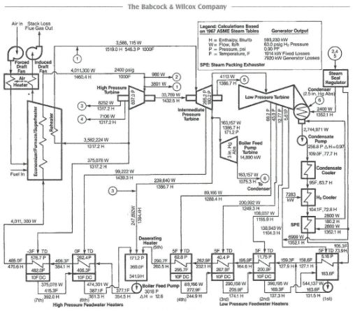
Note the progression from low- to intermediate- to high-pressure steam per the corresponding feedwater heaters. In all cases, the steam has performed some work in the turbine before being extracted for feedwater heating.
Also shown are the general locations of the forced and induced draft fans, which maintain a balanced air flow through the boiler.
References
Tomei, G.L., Ed., Steam, its generation and use, 42nd edition, The Babcock & Wilcox Company, Barberton, Ohio, 2015.
Appendix 4-2
For high-pressure steam generators, especially those that drive turbines, diligent chemistry control is necessary to minimize corrosion and fouling of boilers, superheaters/reheaters, and turbines. During the period of conventional coal-fired power construction and generation in the 20th century, many lessons were learned regarding the criticality of water/steam chemistry monitoring. Some lessons were quite dramatic, resulting not only in lost production and equipment repair but sometimes in injuries and fatalities. From these events, continuous on-line chemistry monitoring became common at most plants. Now, for both power and industrial plant steam production, heat recovery steam generators (HRSGs) are a common choice. This appendix provides an overview of typical on-line instrumentation and water/steam chemistry guidelines for combined cycle plants.
A Brief Review of HRSG Design
While high-purity water requirements and water/steam chemistry control and monitoring for HRSGs are similar to those for older, conventional steam generators, there are some obvious major differences in HRSG design and operation, the most important of which include:
- The various waterwall tube and superheat/reheat panels, aka harps, are aligned in sections along the flue gas path. The waterwall tubes in a coal unit typically form the walls of a box that surrounds the combustion chamber.
- Whereas the waterwall tubes in coal units are exposed to radiant heat as well as convective and conductive heat transfer, during normal operation, HRSG tubes transfer energy only by convection and conduction. Some HRSGs have duct burners, but these operate infrequently, mostly during times of high electrical demand.
- HRSGs are typically of multi-pressure design, with the most popular having three steam-generating networks, aka evaporators.
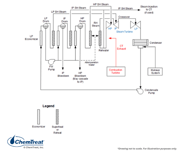
Other than a small amount of steam generation, the LP evaporator essentially serves as a feedwater heater for the IP and HP circuits.
The following sections now outline recommended monitoring parameters of the various circuits within an HRSG per the design shown above.
Sampling Points and Monitoring Parameters
The samples of primary importance throughout the steam-generating network are:
- Makeup treatment system
- Condensate pump discharge
- Condensate return, when applicable
- Feedwater or economizer inlet
- Boiler water
- Saturated steam
- Main and reheat steam
Makeup Treatment System
No system is completely closed, and even in the tightest steam generators a small amount of process water/steam continually escapes. The most common core process of utility makeup systems is reverse osmosis (RO) followed by either mixed-bed ion exchange (MBIX) or electrodeionization (EDI) to “polish” the RO effluent, especially for high-pressure steam generators. RO units typically include a number of instruments to monitor system performance, including pressure, temperature, flow, and specific conductivity. This section focuses on the recommended analyses of the final effluent from either the MBIX or EDI polisher.
Note: In this and the following sections, the normal upper limit, or a range, for each parameter is included.
- Specific conductivity: ≤0.1 µS/cm
- Silica: ≤10 parts per billion (ppb)
- Sodium: ≤2 ppb
These measurements ensure that high-purity water is being distributed to the steam generators. A rise in any of the values indicates that either the MBIX resin has reached exhaustion or a problem has occurred in the EDI unit. Prompt corrective action is necessary.
Condensate Pump Discharge (CPD)
In stand-alone steam generation power units, the primary location for potential contaminant ingress is the condenser, particularly water-cooled condensers where tube leaks allow cooling water to infiltrate the high-purity condensate. A tube leak will introduce a variety of impurities, including hardness ions, chloride and sulfate, and silica, which, when subjected to the harsh environment in the steam generator, can cause serious problems. A condensate polisher will provide a buffer against contaminant ingress, but polishers are often not considered for drum units to reduce capital cost.
Recommended continuous CPD analyses are:
- Cation conductivity (CACE): ≤0.2 µS/cm
- Specific conductivity (SC): Consistent with pH
- Sodium: ≤2 ppb
- Dissolved oxygen: ≤20 ppb
- pH: 9.6–10.0 (This is the pH range for the HRSG design in Figure 1. The range may be a bit lower for other HRSG designs.)
Sodium monitoring is highly effective for detecting condenser tube leaks. With a tight condenser, sodium levels in the condensate are normally very low (<2 ppb), and in many cases, <1 ppb. A rise in sodium provides the earliest indication of a condenser tube leak.
Cation conductivity is now often referred to as conductivity after cation exchange (CACE) to represent the fact that the sample is routed through a cation exchange column to replace all cations, e.g., ammonium, sodium, calcium, etc., with hydrogen ions. This creates a very dilute acid solution of primarily trace amounts of chloride and sulfate ions, whose conductivity is then measured. As with sodium, a rise in CACE indicates impurity in-leakage, although this measurement is also influenced by carbon dioxide ingress, most often from air in-leakage at the condenser. Thus, degasified CACE is becoming increasingly popular , as it utilizes either a re-boiler or nitrogen sparging compartment to remove CO2. A low CACE value is a requirement for proper control of AVT(O) chemistry, which is outlined in the main text.
Dissolved oxygen (D.O.) analyses are important for monitoring condenser air in-leakage. A sudden increase in dissolved oxygen may indicate a mechanical or structural failure at or near the condenser, which allows excess air to enter the system. However, with modern AVT(O) chemistry, some dissolved oxygen is required for the chemistry to be effective.
With regard to specific conductivity and pH, ammonia (or sometimes an amine or ammonia/amine blend) is the pH-conditioning agent for condensate/feedwater. Direct pH measurement of high-purity water can be tricky, and algorithms have been developed to calculate pH based on conductivity measurements to provide more accurate results. Specific conductivity (SC) in high-purity water is directly correlated to the ammonia concentration, and thus, SC measurements offer better control of ammonia feed than pH.
A parameter not typically monitored continuously, but which can be of major importance is total organic carbon (TOC), as discussed in the next section. For utility steam generators, the recommended TOC limit in the CPD is 100 ppb.
Condensate Return
Steam recovered as condensate from process heat exchangers represents a potentially large source of impurities, which, depending of course on the processes and products of the facility, can be inorganic or organic in nature, or may be of particulate form such as iron oxides. Contaminant ingress from condensate return can be very problematic. For high-pressure steam generators, the condensate return should have water purity equivalent to the parameters outlined above for the CPD.
LP Economizer Inlet/Boiler Feed Pump Discharge
The main text discusses AVT(R) and AVT(O) feedwater chemistry programs. The following list outlines the additional recommended feedwater monitoring parameters for AVT(O) chemistry.
- CACE: ≤0.2 µS/cm
- SC: Consistent with pH
- Sodium: ≤2 ppb
- D.O. (range): 5–10 ppb
- pH: 9.6–10.0 (This is the pH range for the HRSG design shown in Figure 1. The range may be a bit lower for other HRSG designs.)
- Iron: ≤2 ppb
Discussion for CACE, SC, pH, and sodium mirrors that for the condensate pump discharge. These measurements, along with dissolved oxygen, are critical for proper AVT(O) chemistry.
Note the inclusion of iron in this list. Iron monitoring provides a direct measurement of FAC (or hopefully lack thereof) and the effectiveness of the feedwater chemistry program. Typically, 90%or greater of iron corrosion products are particulate in nature. Several methods exist to monitor carbon steel corrosion, including:
- Continuous particulate monitoring
- Corrosion product sampling
- Grab sample analysis
Improved grab sampling techniques allow for iron measurements down to 1 ppb with proper sample treatment. This method can provide near real-time data of corrosion rates, although on a snapshot basis.
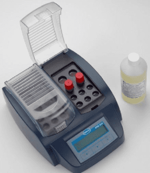
Evaporator Water
Evaporator water sampling is critical for two primary reasons. First, poor chemistry control and/or poor monitoring can allow unacceptable carryover of impurities to the steam. Secondly, as with conventional units, the highest heat fluxes occur within the evaporators, particularly the HP evaporator of HRSGs. Thus, the effects of impurity ingress or poor chemistry control are magnified by the high temperatures and pressures in these circuits. Consider the classic issue of hydrogen damage, which has plagued high-pressure units for decades.
In this mechanism, the most serious corrosive agent, chloride, which may enter during a condenser cooling leak, can concentrate under waterwall tube deposits and generate acid. The following equation outlines a common mechanism:
MgCl2 + 2H2O → Mg(OH)2↓ + 2HCl
Acid generation and subsequent metal corrosion are problematic in their own right, but the very small hydrogen atoms will penetrate the steel matrix and then react with carbon in the steel.
4H + C → CH4
Formation of voluminous methane molecules induces cracking, which can then induce failures with very little metal loss.
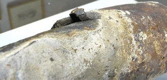
Hydrogen damage remains one of the leading corrosion mechanisms in modern steam generators, which is why, as the list below indicates, immediate unit shutdown is required if the boiler water pH drops below 8.0.
Recommended boiler water analyses include:
- pH (<8.0, immediate boiler shutdown)
- CACE
- Specific conductivity
- Chloride
- Silica
- Phosphate (for those units on phosphate treatment)
- Iron: <5 ppb
No direct limits are shown for most parameters, as the limits are variable based on boiler pressure. EPRI has published detailed charts for these parameters, but they are only directly available to EPRI members. Other guidelines are available from the International Association of the Properties of Water and Steam (IAPWS) at no charge.
Also notice the limit for iron. The LP circuits and some IP locations in an HRSG can suffer from two-phase FAC. Iron monitoring is important to ensure proper chemistry is being maintained in these circuits.
A note on phosphate: For decades, tri-sodium phosphate (Na3PO4) has been a core boiler water treatment chemical in many drum units. However, controlling phosphate concentration is difficult due to the compound’s reverse solubility above 300°F. For high-pressure utility units, modern programs typically call for a maximum phosphate concentration <2.4 ppm, and many chemists hold the concentration well below that level.
Some plant personnel, especially in the power industry, have switched to caustic (NaOH) feed to eliminate phosphate “hideout,” but great care is required with these programs to prevent caustic gouging of waterwall tubes. Including a condensate polisher in the system design offers the opportunity to eliminate phosphate or caustic from the boiler water treatment program.
Steam
Steam purity measurements are very important, particularly if the steam drives a turbine or turbines. Contaminant deposition on turbine blades can lead to corrosion and possible blade failures, which represent a potentially catastrophic situation with the turbine spinning at several thousand rpm. Core monitoring parameters include the following:
- CACE: ≤0.2 µS/cm
- Sodium: ≤2 ppb
- Silica: ≤10 ppb
Sodium provides a direct indication of salt or sodium hydroxide carryover with the steam. Salts, particularly chloride salts, will settle in the last rows of the low-pressure turbine, where they can cause pitting and subsequent stress corrosion cracking (SCC) and corrosion fatigue (CF) of turbine blades and rotors. Sodium hydroxide carryover is a very serious issue, as caustic can quickly induce SCC of turbine components.
CACE provides an indirect measurement of chloride and sulfate carryover and has been a long-time guideline for turbine manufacturers. However, the accuracy of CACE is suspect, especially given that the limit for both impurities is 2 ppb, similar to sodium. One instrument that became recently available analyzes these two impurities down to a 0.1 ppb level.
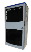
The instrument separates ions in the sample via the process of capillary electrophoresis. The ions are then measured by a conductivity analyzer.
It has long been known that silica in steam will precipitate on turbine blades. While the compound is not corrosive, it can influence turbine aerodynamics and reduce efficiency, hence the 10-ppb recommended limit.
Several steam sampling points are available in power generating units. These include saturated, main, and reheat steam samples. Main and reheat steam are the most important, as they provide data on impurities directly entering the turbine, which can also come from contaminated steam attemperation water. Measurement of saturated steam is less important but can be valuable on a periodic basis to check for mechanical carryover issues from steam drums. Failed or damaged steam separators are a common cause of mechanical carryover.
References
- Cycle Chemistry Guidelines for Combined-Cycle/Heat Recovery Steam Generators (HRSGs), EPRI, Palo Alto, CA: 2006. 1010438. Note: EPRI published an updated version of this document in 2013.
- Buecker, B. and S. Shulder, “Power Plant Cycle Chemistry Fundamentals”; pre-conference seminar to the 35th Annual Electric Utility Chemistry Workshop, June 2, 2015, Champaign, Illinois.
About the Authors

Luis Carvalho
Founder and Owner of Industrial Water Treatment Academy (iwtA)
Luis Carvalho is a Chemical Engineer and a Licensed Professional Engineer in Ontario, Canada with over 35 years of broad-based industrial water treatment. His knowledge base includes high-pressure boiler cycle chemistry, including FAC, RO, UF, EDI, and cooling water technology. He is the Founder and Owner of the Industrial Water Treatment Academy (iwtA) and recently held the position of Principal Engineer at ChemTreat for 8 years, where he was responsible for technical leadership in high-pressure boiler treatment across a myriad of industries worldwide. Luis played a significant role in defining new criteria for steam purity for use in turbines and introducing changes to decades-long steam purity guidelines. He won the Paul Cohen Award in 2006 at the International Water Conference. In 2018, Luis was the Chair of the Technical Subcommittee on Air In-leakage in Steam-Water Systems at the International Association of the Properties of Water & Steam (IAPWS).

Tom Nix
Senior Technical Staff Consultant
Tom Nix is a trusted technical expert with decades of industrial water treatment experience. Nix is well-versed in a wide range of applications, including influent clarification, softening, demineralization, reverse osmosis, cooling water treatment, low- and high-pressure boiler treatment, and wastewater treatment. He holds a B.S. in Environmental Biology from the University of Texas at Austin.

Brad Buecker
President of Buecker & Associates, LLC
Brad Buecker is president of Buecker & Associates, LLC, and most recently he served as Senior Technical Publicist with ChemTreat, Inc. He has over four decades of experience in or supporting the power industry, much of it in steam generation chemistry, water treatment, and air quality control. Buecker has a B.S. in Chemistry from Iowa State University. He has authored or co-authored over 250 articles for various technical trade magazines and has written three books on power plant chemistry and air pollution control. He serves on the Editorial Advisory Board of Water Technology and is a member of the ACS, AIChE, AIST, ASME, NACE (now AMPP), and the Electric Utility Chemistry Workshop planning committee.
Acknowledgements
The ChemTreat Water Essentials Handbook would not have been possible without the contributions of many people. See the full list of contributors.