By Brad Buecker, ChemTreat, Inc. and Ken Kuruc, Hach
This article was originally published in PPCHEM® Journal; PPCHEM® 2020, 22(4), 142–150; https://journal.ppchem.com/
Abstract
Although thousands of low-pressure steam generators exist at industrial plants around the globe, the chemistry of such units has not received the same attention as that of high-pressure units. The conditions in these steam generators are typically not as harsh as in utility units, yet water/steam chemistry control is still very important for the plants’ steam/condensate systems. This article discusses many of the most important sampling points and parameters for industrial steam generators, and it illustrates the benefits of proper chemistry control to maintaining equipment reliability and availability.
Introduction to Sampling Points and Parameters for Low-Pressure Industrial Steam Generators
For over two decades, the PPCHEM® journal has offered informative articles from world-class experts on high-pressure steam generation chemistry. The knowledge provided has been of great benefit to many power plant chemists and technical personnel. However, the contributors of this article recognize that thousands of low-pressure steam generators exist at industrial plants around the globe. Even though conditions in these steam generators are typically not as harsh as in utility units, water/steam chemistry control is still very important. Yet, the authors have frequently observed that some industrial plant owners, operators, and technical personnel focus on process engineering and chemistry, rather to the neglect of the plant’s steam/condensate systems. This article outlines many of the most important sampling points and parameters for industrial steam generators, and it illustrates the benefits of proper chemistry control to maintaining equipment reliability and availability.
Industrial Steam Generating Circuitry
Figure 1 below illustrates a general schematic of a common industrial steam generation/condensate return system. Obviously, any number of alternatives or nuances to this arrangement may exist depending upon the nature of the products generated and required conditions of the steam. However, the schematic provides a good foundation for this discussion. In this article, the authors will mostly consider steam generators less than 4.14MPa (600 psig) in pressure.
The following text progresses through the numbered sample points, with some commentary about the evolution of chemical treatment advancements that offer improvement over former technologies. An important point to note in the diagram and in the discussion below is that continuous sampling is recommended at several locations. Continuous water/steam chemistry monitoring is, of course, important for high-pressure/temperature power generating units, but even in these lower pressure systems some upsets can cause serious damage in short order which cannot be detected in a timely manner with grab sampling alone.
In order to gain pertinent and valuable information from the sample taken, one must be certain that the sample obtained is representative of the species within the loop. This is true both for grab samples and with on-line monitoring. Especially of concern is the requirement that the velocity of the fluid entering the sample nozzle port be exactly the same as the velocity of the stream being sampled, otherwise known as isokinetic sampling. The International Association for the Properties of Water and Steam (IAPWS) has generated a technical guidance document (TGD) which addresses the challenges of making these measurements [1].
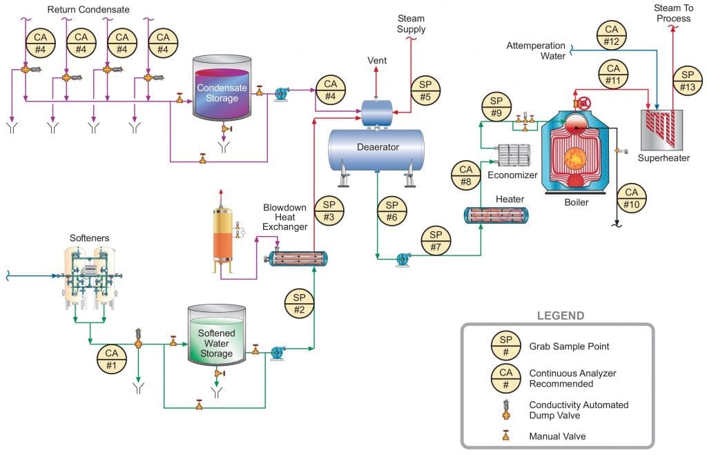
Figure 1. General schematic of recommended sample points for industrial process steam flow and condensate return.
Makeup System Effluent Quality #1
A quite common makeup system design at many plants, at least in the United States, has relied on sodium softening of the inlet plant water, whose source is often municipal potable water. These makeup supplies are generally free of suspended solids (except perhaps those picked up by some corrosion of carbon steel pipes), and primarily contain the dissolved ions from the original source. Often, a significant portion of the hardness has already been removed at the water plant via lime softening. However, even these waters, although suitable for drinking, require further treatment for hardness removal. Eq. (1) below outlines the most common scale-forming mechanism that can occur in steam generators unless hardness is reduced.
Ca2+ + 2HCO3– + heat → CaCO3↓ + CO2 + H2O (1)
Calcium carbonate (CaCO3) is inversely soluble with temperature, and thus solutions containing calcium and bicarbonate alkalinity, which may be fine at ambient conditions, can cause significant scaling in hot water systems, boilers, and other heat exchangers (see Figure 2).
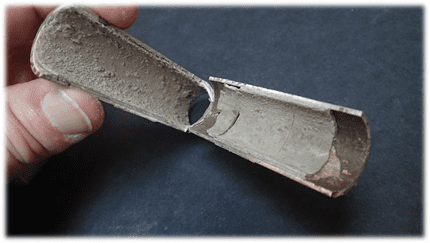
Figure 2. Calcium carbonate scale in a heat exchanger tube.
One of the authors was once employed at a chemical plant where the incoming makeup was split into two streams, one with sodium softening treatment for part of the manufacturing process and the other with reverse osmosis (RO) followed by cation and anion exchange polishing for high-purity needs. To ensure reliable output from the softeners, plant personnel installed a continuous calcium monitor on the softener effluent, whose detection limit was 1μg·L–1.
Even a softener that is well maintained and operated still allows the other ions in the makeup to reach the boiler, and these may cause difficulties.
For example, bicarbonate alkalinity, upon reaching the boiler, is in large measure converted to CO2 via the following reactions (Eqs. (2) and (3)):
2HCO3– + heat → CO32– + CO2↑ + H2O (2)
CO32– + heat → CO2↑ + OH– (3)
The total conversion of CO2 from the combined reactions may reach 90%. CO2 flashes off with the steam, and when the CO2 re-dissolves in the condensate it can increase the acidity of the condensate return.
CO2 + H2O ⇔ H2CO3 ⇔ H+ + HCO3– (4)
Although the acidity generated by this reaction has a relatively mild lower limit (minimum pH above 5), it is more than enough to cause significant corrosion of carbon steel in condensate return systems. If dissolved oxygen is present, corrosion can be greatly magnified.
Other impurities that can enter the steam generation system with sodium softening as the only makeup treatment include chloride and sulfate salts, and silica. These compounds can potentially influence corrosion and steam purity. As a result of the development of reliable membrane-based technologies, RO offers a solid alternative and upgrade to softening, where even basic systems can remove 99% of all ions from water. Analytical instrumentation for RO units is typically included with the system as outlined in Figure 3.
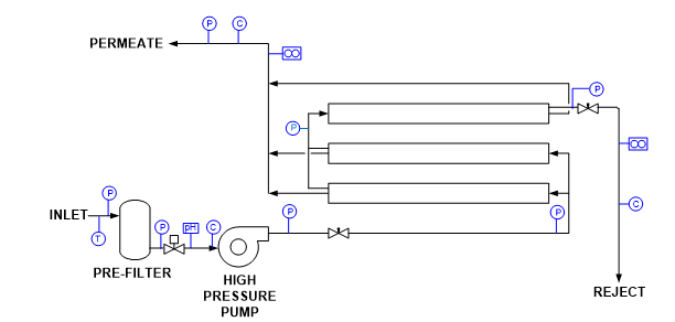
Figure 3. Common RO instrumentation.
T = temperature
P = pressure
C = specific conductivity
Instrument outputs can be connected to both local and distributed control system (DCS) networks for monitoring and operational purposes. Alarms and, if necessary, automatic unit shutdown are possible for a number of conditions. Some of the most important include [2]:
- Low inlet pressure
- High/low pH
- High temperature
- High permeate pressure
- High permeate conductivity
- Low concentrate flow
Another measurement that can be beneficial upstream of an RO unit is oxidation-reduction potential (ORP) to protect the membranes from an excursion of an oxidizing biocide, which could cause severe damage.
Makeup to the Deaerator (#2 and #3)
Only grab sample analyses are shown for these sampling points, as under normal conditions the chemistry should not change from that produced by the makeup water treatment system. On occasion, however, makeup storage tanks have become contaminated from unusual circumstances. Figure 1 also shows a heat exchanger to recover energy from the boiler blowdown. These exchangers are not always present. If an exchanger develops a leak, the boiler blowdown will be of worse quality than the makeup and will contaminate the feedwater.
Condensate Return (#4)
For the following discussion of sample point 4 (and also #6 through #10), Table 1 is a good guide. It outlines data extracted from [4], which has been a long-term guide to water quality limits for industrial boilers in the United States.
Given the enormous variety of products that come from chemical plants, refineries, steel mills, acid production facilities, and others, multiple impurities from leaking heat exchangers or reaction vessels could be present in condensate return. A classic case history comes from an organic chemical plant that one of the authors and a former colleague visited a number of years ago. The superheaters of four 3.79MPa (550 psig) package boilers had to be replaced every 1.5 to 2 years due to excessive deposition and overheating. An initial walkaround revealed foam exiting from the saturated steam sample line of each boiler. A review of water chemistry data provided by an outside vendor indicated total organic carbon (TOC) concentrations in the condensate return as high as 200mg·L–1. Contrast this value with the 0.05mg·L–1 feedwater limit recommended in Table 1. The high organics caused severe foaming in the boiler drums and carryover of compounds to the steam. Unlike the layout shown in Figure 1, the condensate return had no on-line instrumentation and no automatic dump system to discard contaminated condensate.
Depending upon the potential impurity ingress to the condensate return, a number of different instruments might be suitable for monitoring condensate return. Specific conductivity and cation conductivity (now often designated as conductivity after cation exchange (CACE)) come quickly to mind, as they can provide a general indication of contamination, with CACE helping to account for the influence of ammonia or neutralizing amines utilized to adjust pH (additional discussion of pH monitoring and control is included below). For the case history mentioned above, TOC analyses could have been beneficial. An additional application where TOC analyzers can be valuable is on the steam/condensate systems at liquified natural gas (LNG) import and export facilities. Yet another potentially very useful analytical measurement at refineries, petrochemical plants, and such is oil-in-water [5]. Many sources of oil or hydrocarbon ingress to condensate (and cooling water) are possible at these facilities.
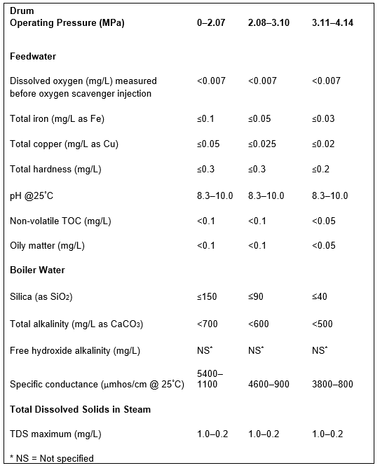
Table 1. Guidelines for impurity limits in low-pressure industrial boilers. This data was extracted from Table 1 in Reference 3. The booklet contains many additional details regarding industrial boiler water guidelines.
Deaerator Inlet Steam (#5)
A sample tap on this line allows periodic checks of steam purity to the deaerator. However, the steam supplied to the deaerator will be extracted from the main steam, whose recommended analyses are outlined later in this article. With that instrumentation in place, sampling of #5 should not normally be required.
Boiler Feedwater (#6 to #9)
Many articles have appeared in the PPCHEM® journal and elsewhere over the last several decades about feedwater chemistry for high-pressure steam generators and the need to minimize flow-accelerated corrosion (FAC) [6]. For those units that do not have any copper alloys in the condensate/feedwater system, treatment chemistry has evolved to either all-volatile treatment oxidizing (AVT(O)) or oxygenated treatment (OT), where the presence of some oxygen is required to generate the correct oxide layer on carbon steel surfaces. However, AVT(O) and especially OT require high-purity makeup water (CACE < 0.2μS·cm–1 for AVT(O) and <0.15μS·cm–1 for OT), as otherwise serious oxygen corrosion will result. This is a luxury not common at many industrial facilities. Accordingly, a well-maintained and -operated deaerator is a critical component of the feedwater network. As is common with utility steam generators, Figure 1 shows continuous analysis at the economizer inlet #8. One of these measurements is, of course, dissolved oxygen (DO). A properly operating deaerator should reduce dissolved oxygen concentrations to 7μg·L–1. Supplemental chemical oxygen scavengers/reducing agents may be utilized to lower the DO concentration even further. Use of a portable DO meter at sample points #6 and #7 can help to confirm on-line readings, or to troubleshoot air ingress at the boiler feed pumps. Continuous DO analysis of sample #8 is also recommended.
Note: Sample point #9 is an even better location than #8, but in the authors’ experience this sample point, the economizer outlet, is often not available.
However, a question that can be justifiably posed is, “Can FAC also occur in industrial feedwater systems, particularly if dissolved oxygen is reduced to very low levels?” The answer is yes, but in many cases AVT(O) or OT are not acceptable due to higher-than-allowed dissolved solids (for these programs), which are often present in industrial boiler makeup and feedwater. Research and operation in utility units has shown that pH has a strong influence on FAC, and so FAC control can in large measure be approached in that regard.
Guidelines developed by the Electric Power Research Institute (EPRI), the International Association for the Properties of Water and Steam (IAPWS) and others recommend a feedwater pH above 9.0, and typically at least in a mid-9 range, for power plant units. Steel corrosion is greatly reduced at these alkalinity levels. While Table 1 suggests a pH range of 8.3–10.0 for industrial boilers, the lower limit can probably be raised, preferably towards the ranges recommended for power units and indicative of the data shown in Figure 4.
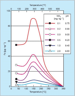
Figure 4: Influence of pH and temperature on iron dissolution from carbon steel [3].
In the power industry, the common feedwater pH-conditioning chemical is ammonia, which elevates pH via the reaction shown in Eq. (5):
NH3 + H2O⇔NH4 + OH– (5)
Ammonia addition to water is an equilibrium reaction and thus the pH increase is limited. But ammonia is quite volatile, and the compound significantly partitions with steam in low-pressure boilers. For industrial units, neutralizing amines are a common alternative to ammonia for feedwater pH conditioning.
Developing the best program for comprehensive system protection has sometimes been difficult with these compounds, as each has a different basicity and distribution ratio (see Table 2). Many industrial steam generation/condensate return systems are quite complex, where it is desirable to have proper pH control throughout the network, but in which a single compound is not sufficient. The authors’ colleagues have developed blended amine products that can provide wide-ranging coverage. However, a thorough analysis of system design, metallurgy, current chemistry, and operating temperatures is a pre-requisite for selection of the proper program.
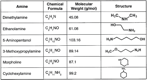
Table 2. Common neutralizing amines
Another question that arises concerns pH monitoring. Measurement of pH is difficult in high-purity waters (generally understood to have conductivity values <2μS·cm–1), and for high-pressure steam generators algorithms have been developed that calculate pH based on specific conductivity and CACE measurements. These are accurate within the typical recommended feedwater pH ranges. But, with lower-purity industrial boiler feedwaters, direct pH measurements are more reliable. Thus, pH is an on-line measurement recommended for sample point #8 or #9, if available.
Iron monitoring of sample points #6, #7, and #8 or #9 is highly recommended to track feedwater corrosion and evaluate the performance of chemical treatment programs. Similarly, regular iron monitoring of condensate return (#4) should be considered, in large measure to ensure that chemical treatment programs are protecting the often very large carbon steel piping networks.
Note: Copper alloys are often a prime material for heat exchanger tubes. Space limitations prevent a discussion of chemical treatment methods for these materials, but periodic grab sample analyses for copper are recommended for systems that have copper alloys to ensure that the treatment program is performing properly.
As the authors have reported previously [7,8], simple colorimetric lab methods have traditionally been used to monitor dissolved iron contamination. The common colorimetric method for dissolved iron is based on the extremely sensitive ferrozine ferrous iron complex described
by Stookey [9]. Ferrozine complexes with dissolved ferrous iron to form an intensely colored purple complex. The dissolved ferrous iron concentration may be determined by measuring the absorbance of this complex. Modifications of this traditional method now allow for the determination of both dissolved iron and particulate iron oxides at very low concentrations.
The reductive dissolution of iron oxides via thiol-containing compounds has been thoroughly investigated by Waite et al. Thioglycolic acid (TGA) has been used to successfully dissolve and reduce various iron oxides. While magnetite is dissolved relatively easily with TGA, hematite has been shown to be much more resistant to this method [10,11]. However, TGA is compatible with the sensitive ferrozine reagent and is commercially available as a combined reagent. This combination digestion-reduction-detection reagent is particularly useful for simplifying analysis and minimizing contamination.
Complete dissolution of particulate magnetite and hematite can be achieved with a 135°C, 30-min closed vessel digestion using 240μL of combination reagent and 12mL of sample. The digestion is carried out in a 20mL glass vial heated in an aluminum block. After the sample has cooled, the absorbance is determined with a spectrophotometer and a 1in. (2.54 cm) cell (see Figure 5). The calibrated range using this procedure is 1–100μg·L–1 with a method detection limit (MDL) of 0.3μg·L–1.
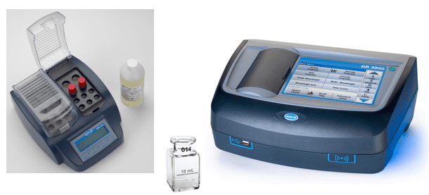
Figure 5. Combination reagent, digestion vials, and heater block (left); 1-inch sample cell (center) and spectrophotometer (right).
On-line methods are available for iron monitoring, including those based on nephelometry, but these are often beyond the budget at industrial plants. IAPWS has generated a TGD which discusses the variety of analytical methods that can be used for iron [12].
Boiler Blowdown (#10)
The choice of analyzers for boiler blowdown can be challenging, because with low-pressure units a variety of treatment programs are possible. In the 1930s, as power generating units increased in number and size, tri-sodium phosphate (Na3PO4, also known as TSP) became a popular boiler pH conditioning chemical for drum boilers.
Na3PO4 + H2O⇔NaH2PO4 + NaOH (6)
In the power industry, phosphate treatment programs have undergone much evolution from TSP to coordinated and congruent programs, with a return to TSP only, albeit in low dosages. For industrial boilers, phosphate treatment methods remain a strong choice, but are not always limited just to TSP. The lower temperatures may allow chemistry along the lines of the old coordinated phosphate programs, with sodium-to-phosphate ratios less than 3:1. A second function of phosphate, which is particularly important for units in which hardness ions may periodically ingress, is to control scale formation. Phosphate and the alkalinity produced by its reaction with water (see Eq. (6)) react with hardness ions to, at least to some extent, form soft sludges as opposed to hard scale.
Often recommended with phosphate treatment are sludge conditioners consisting of water-soluble polymers that help to keep solids in suspension by a combination of dispersion, crystal modification, and sequestration. Iron particulates from condensate return system corrosion can be problematic, where sludge conditioners help to keep the particles in suspension for subsequent blowdown. These polymers can sometimes serve as a stand-alone treatment, particularly if hardness ingress is not an issue. Polymer formulations frequently include an alkalinity builder to maintain pH in a mildly basic pH range similar to phosphate.
Chelant chemistry has at times been successfully employed in industrial drum units, in which the chemicals directly bind with metals to keep them suspended. Ethylenediaminetetraacetic acid (EDTA) is the most widely known chelant. However, improper use of chelants can cause localized corrosion of boiler components.
So, analytical parameters for industrial drum units obviously include pH and phosphate, if that chemical is utilized. As with utility boilers, specific and cation conductivity are important measurements to determine the general concentration of dissolved solids in the boiler and adjust blowdown accordingly. Monitoring of polymer concentrations has been improved with the development of tagged products that respond to fluorescence.
Saturated Steam (#11)
In general, steam purity in low-pressure boilers is not problematic because the risk of carryover, as compared to high-pressure utility units, is lessened due to the lower pressures and temperatures. However, as the case history that introduced the condensate return section outlined, carryover issues cannot be ignored. In that instance, the organic impurities initiated foaming and subsequent carryover, but other issues that can induce carryover include damaged or failed steam separating components in the boiler drum, sudden load swings that cause surging, excessive mineral content in the boiler water, poor drum design, lack of operator attention to water levels, and so on. A common grab sample analysis in the power industry is sodium, as this element can be measured with excellent accuracy. Concentrations in a low μg·L–1 range should be the norm. According to Table 1, total dissolved solids (TDS) is another analytical parameter, although these analyses require time to filter the sample, weigh the resultant liquid and container, and then dry it to completion and re-weigh the container with the dried solids. Saturated steam is the most difficult fluid in a steam generator to sample accurately, as the steam is very close to two-phase conditions that can introduce inaccuracies unless rigorous sampling techniques are employed. This includes the use of an isokinetic sampling device in the steam line. Again, refer to reference [1].
Superheated Steam (#12)
In the power industry, superheated steam, and ideally reheat steam, is the best choice for online analyses. Reheat sampling accounts for all prior effects, including attemperation, that can influence the steam, and is particularly important to protect the intricate and precisely machined turbine(s) downstream. This layout contrasts with industrial boilers, which normally do not have reheaters and often may not drive turbines or have attemperation. Several of these scenarios are examined below.
The steam purity guidelines shown in Table 1 only include one parameter, TDS. This is not an analysis that can be performed on-line. Some continuous on-line analyses are necessary to guard against upsets that could cause problems in downstream equipment. One possibility is CACE, which is a general indication of salt (primarily chlorides and sulfates) carryover in the steam. Sodium is another reliable and relatively inexpensive measurement for monitoring mechanical carryover. For situations like that outlined in the earlier case history, TOC is a potential choice.
The situation becomes more complex if some of the steam also drives turbines. The instrumentation mentioned above would definitely be in order, and for higher-pressure boilers such as might be found at a co-generation plant could include silica. Silica (SiO2) is a vaporous carryover product, where the carryover effects decidedly increase with increasing pressure. Silica precipitates on turbine blades, and while not corrosive can negatively impact the aerodynamic efficiency of the turbine.
Regarding the attemperation line shown in Figure 1, steam attemperation should only be employed if high-purity water (sodium, chloride, and sulfate concentrations of less than 2μg·L–1) is available for the attemperation sprays. Introduction of impurity-laden water directly to steam can quickly cause serious problems. In power units, attemperation water is usually taken from the boiler feed pump discharge, which provides enough pressure to overcome that of the steam. Thus, feedwater analyses also provide data on the purity of the attemperation sprays. If another source is utilized, then the attemperation water should have its own set of continuous analyzers, with sodium and CACE being prime candidates.
References
[1] Technical Guidance Document: Procedures for the Measurement of Carryover of Boiler Water into Steam, 2008. International Association for the Properties of Water and Steam, IAPWS TGD1-08. Available from http://www.iapws.org.
[2] Byrne, W., Reverse Osmosis, A Practical Guide for Industrial Users, 2002. Tall Oaks Publishing, Inc., Littleton, CO, USA, 2nd Edition.
[3] Sturla, P., “Oxidation and Deposition Phenomena in Forced Circulating Boilers and Feedwater Treatment”, presented at the Fifth National Feedwater Conference, 1973 (Prague, Czechoslovak Socialist Republic).
[4] Consensus on Operating Practices for the Control of Feedwater and Boiler Water Chemistry in Modern Industrial Boilers, 1994. The American Society of Mechanical Engineers, New York, NY, USA, CRTD 34.
[5] Monitoring Leaks in Heat Exchangers, 1995. Turner Designs Hydrocarbon Instruments, Fresno, CA, USA.
[6] Dooley, B., Lister, D., “Flow-Accelerated Corrosion in Steam Generating Plants”, PowerPlant Chemistry 2018, 20(4), 194.
[7] Kuruc, K., Johnson, L., “Further Advances in Monitoring Low-Level Iron in the Steam Cycle”, PowerPlant Chemistry 2015, 17(2), 94.
[8] Buecker, B., Kuruc, K., Johnson, L., The Integral Benefits of Iron Monitoring for Steam Generation Chemistry Control, 2019. Available from https://www.power-eng.com.
[9] Stookey, L. L., “Ferrozine – A New Spectrophotometric
Reagent for Iron”, Analytical Chemistry 1970, 42(7), 779.
[10] Waite, T. D., Torikov, A., Smith, J. D., “Photoassisted
Dissolution of Colloidal Iron Oxides by Thiol-Containing Compounds: I.
Dissolution of Hematite (α-Fe2O3)”, Journal of Colloid and Interface Science 1986, 112(2), 412.
[11] Baumgartner, E., Blesa, M. A., Maroto, A. J. G., “Kinetics of the Dissolution of Magnetite in Thioglycolic Acid Solutions”, Journal of
the Chemical Society, Dalton Transactions 1982, 1649.
[12] Technical Guidance Document: Corrosion Product Sampling and Analysis for Fossil and Combined Cycle Plants, 2014. International Association for the Properties of Water and Steam, IAPWS TGD6-13(2014). Available from http://www.iapws.org.
The Authors
Brad Buecker (B.S., Chemistry, Iowa State University, Ames, IA, USA) is a senior technical publicist with ChemTreat. He has many years of experience in or affiliated with the power industry, much of it in steam generation chemistry, water treatment, air quality control, and results engineering positions with City Water, Light & Power (Springfield, IL, USA) and the Kansas City Power & Light Company’s (now Evergy) La Cygne, KS, USA, generating station. Most recently he was a technical specialist with Kiewit Engineering Group Inc. He is a member of the American Chemical Society, American Institute of Chemical Engineers, American Society of Mechanical Engineers, Association of Iron and Steel Technology, National Association of Corrosion Engineers, the Electric Utility Chemistry Workshop planning committee, and the Power-Gen International planning committee. Mr. Buecker has authored many articles and three books on power plant topics.
Ken Kuruc (B.S., Chemistry, John Carroll University, Cleveland, OH, USA) has been active in the power industry for over 25 years. In his current role, Ken provides technical support on all aspects of water quality monitoring for fossil power generation sites across the USA. He has co-authored articles which have appeared in various power industry publications and has presented at numerous utility and water chemistry conferences, including the International Water Conference, where he was awarded the 2019 Paul Cohen Award.